Plasmonic Device Tuned using Liquid Crystal Molecule Dipole Control

a plasmonic display and liquid crystal molecule technology, applied in liquid crystal compositions, instruments, chemistry apparatuses and processes, etc., can solve the problems of wasting the available light energy provided by the surroundings, requiring additional power to overcome the ambient light of the display, and display technologies all have disadvantages or challenges to overcome, so as to achieve fast video applications, enhance the color tuning range of the nanoplasmonic display, and enhance the effect of the color tuning rang

Inactive Publication Date: 2011-05-12
SHARP KK
View PDF3 Cites 14 Cited by
  • Summary
  • Abstract
  • Description
  • Claims
  • Application Information

AI Technical Summary

Benefits of technology

[0015]Described herein is a method for the electrical tuning of the refractive index of the surrounding dielectric material. By making use of the tunable refractive index of liquid crystal or other electro-optical materials, the plasmonic resonance of the metal nanostructures can be tuned across the visible range and, thus, a pixel can exhibit different colors under different external voltages. Liquid crystal (LC), for example, has an electrically tunable refractive index. LC has a response time of a few milliseconds or shorter and, therefore, is fast enough for video applications.
[0016]To further enhance the color tuning range of a nanoplasmonic display, the alignment of LC molecules can be controlled using metal nanoparticles. According to basic electromagnetic theory, metal nanoparticles of different shapes and distribution strongly affect the electrical field distribution surrounding them. Since LC molecules are aligned in accordance with the electrical field vectors at their precise locations, the alignment of LC molecules can be controlled by tuning the shape and distribution of metal nanoparticles, as well as the location and shape of electrodes.
[0017]Based on this concept, it is possible to control reflected color by simply applying voltages across different electrodes (e.g., vertically and horizontally). Using a dome-shaped nanoparticle for example, a large wavelength tuning range is achieved by maximizing the effective refractive index change “seen” by the nanoparticle. This particular particle shape, due to the isotropic electrical field distribution, results in little angle dependence in the reflected color.
[0018]Thus, large electromechanical and electro-optical effects can be achieved simultaneously with a low driving voltage. The color-tunable device operates with ambient light and does not normally require backlight illumination. Since ambient illumination is used to render these images, the power requirements of such a display are dramatically less than a standard LCD and, therefore, reduce the power consumption when introduced into devices such as a cellular phone or laptop.

Problems solved by technology

Thus, the available light energy provided by these surroundings is wasted, and in fact, the operation of these displays requires additional power to overcome this ambient light.
These display technologies all have disadvantages or challenges that Must be overcome to obtain greater commercial success.
Many existing technologies rely upon phenomena that are intrinsically slow.
Therefore, display techniques that rely on reactions to switch dye molecules demand unacceptably high currents for displaying video.
In particular, most reflective display technologies can only produce binary color (color / black) from one material set.
This limits the maximum reflected light for some colors to about ⅓, so that the pixels of this type cannot produce saturated colors with a good contrast.
Some reflective displays face reliability problem over a long lifetime.
Achieving the desired number of cycles is particularly difficult in reflective displays using techniques based on chemical reactions, techniques that involve mixing and separation of particles, or MEMS technology that involves repeated mechanic wear or electric stress.
Because of the limited refractive index (n) change of dielectric 106 materials such as liquid crystal, the color tuning range of a device using just this tuning modulation means is very limited.
Research labs have reported liquid crystals with a Δn as high as 0.79, but the performance of such materials is not guaranteed.
Besides, these materials may not have the appropriate response time or threshold voltage required for the nanoplasmonic display application.

Method used


Image

  • Plasmonic Device Tuned using Liquid Crystal Molecule Dipole Control
  • Plasmonic Device Tuned using Liquid Crystal Molecule Dipole Control
  • Plasmonic Device Tuned using Liquid Crystal Molecule Dipole Control

Examples


Embodiment Construction

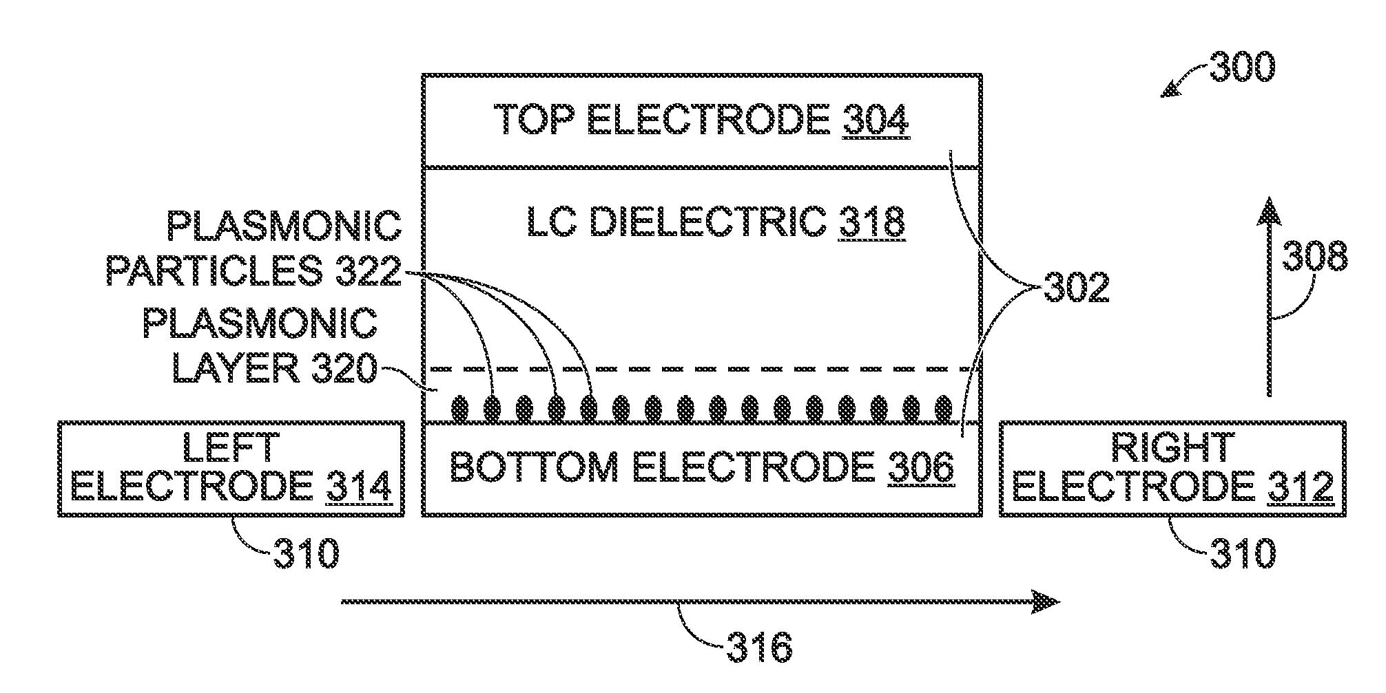
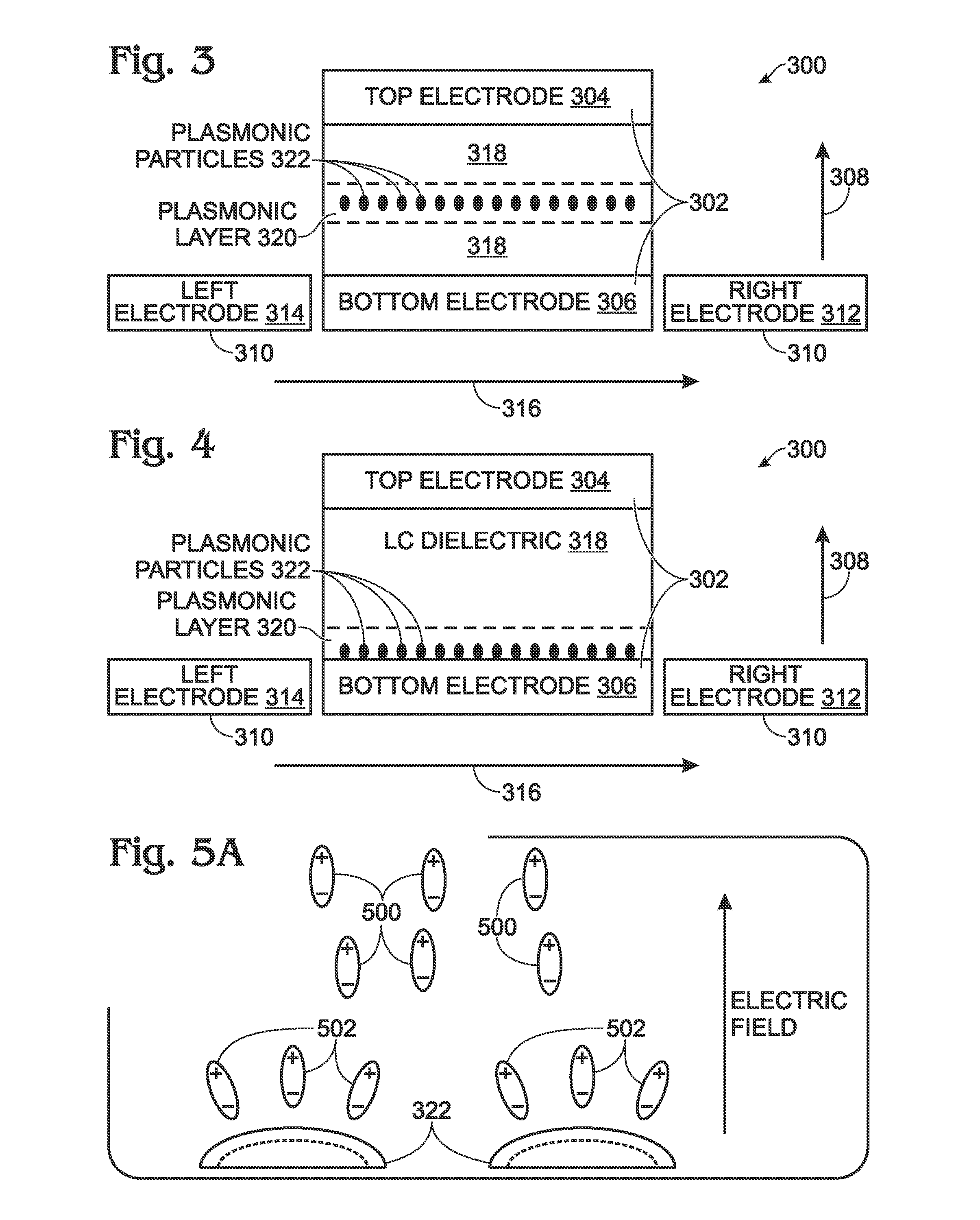
[0036]FIG. 3 is a partial cross-sectional view of a plasmonic display device with liquid crystal dipole molecule control. The device 300 comprises a first set of electrodes 302 including at least one electrically conductive top electrode 304 and at least one electrically conductive bottom electrode 306, capable of generating a first electric field in a first direction 308. A second set of electrodes 310 includes an electrically conductive right electrode 312 and an electrically conductive left electrode 314. The second set of electrodes 310 is capable of generating a second electric field in a second first direction 316. A dielectric layer 318 overlies the bottom electrode 306, made from a liquid crystal material with molecules having dipoles responsive to an electric field. A plasmonic layer 320, including a plurality of discrete plasmonic particles 322, is interposed between the first set of electrodes 302 and second set of electrodes 310, and in contact with the dielectric layer ...


PUM

PropertyMeasurementUnit
sizeaaaaaaaaaa
diameteraaaaaaaaaa
electric fieldaaaaaaaaaa

Abstract

A plasmonic display device is provided with liquid crystal dipole molecule control. The device is made from a first set of electrodes including at least one electrically conductive top electrode and at least one electrically conductive bottom electrode capable of generating a first electric field in a first direction. A second set of electrodes, including an electrically conductive right electrode and an electrically conductive left electrode, is capable of generating a second electric field in a second first direction. A dielectric layer overlies the bottom electrode, made from a liquid crystal material with molecules having dipoles responsive to an electric field. A plasmonic layer, including a plurality of discrete plasmonic particles, is interposed between the first and second set of electrodes and in contact with the dielectric layer. In one aspect, the plasmonic layer is embedded in the dielectric layer.

Description

RELATED APPLICATION[0001]The application is a Continuation-in-Part of a pending application entitled, PLASMONIC DEVICE TUNED USING ELASTIC AND REFRACTIVE MODULATION MECHANISMS, invented by Tang et al., Ser. No. 12 / 621,567, filed on Nov. 19, 2009, Attorney Docket No. SLA2685;[0002]which is a Continuation-in-Part of a pending application entitled, COLOR-TUNABLE PLASMONIC DEVICE WITH A PARTIALLY MODULATED REFRACTIVE INDEX, invented by Tang et al., Ser. No. 12 / 614,368, filed on Nov. 6, 2009, Attorney Docket No. SLA2684. Both the above-referenced applications are incorporated herein by reference.BACKGROUND OF THE INVENTION[0003]1. Field of the Invention[0004]This invention generally relates to electronic visual display devices and, more particularly, to a color-tunable plasmonic display device that relies upon controlling the orientation of molecule dipoles in a liquid crystal refractive medium.[0005]2. Description of the Related Art[0006]Reflective display or color-tunable device techno...

Claims


Application Information

Patent Timeline
Patent Type & Authority Applications(United States)
IPC IPC(8): G02F1/133
CPCG02F1/23G02F2203/34G02F2203/10
Inventor TANG, LIANGHASHIMURA, AKINORIHUANG, JIANDONGVOUTSAS, APOSTOLOS T.
Owner SHARP KK
Why Eureka
Try Eureka