Current collector for non-aqueous electrolyte secondary battery, electrode for non-aqueous electrolyte secondary battery, production methods thereof, and non-aqueous electrolyte secondary battery

a technology of non-aqueous electrolyte and current collector, which is applied in the direction of cell components, final product manufacturing, sustainable manufacturing/processing, etc., can solve the problems of active material layer falling off the current collector, affecting the performance of the electrode, and reducing the adhesion between the active material layer and the current collector, so as to reduce the compressive stress, improve the flexibility, and suppress the current collector from becoming wrinkled or the active material layer

Inactive Publication Date: 2011-05-12
PANASONIC CORP
View PDF8 Cites 51 Cited by
  • Summary
  • Abstract
  • Description
  • Claims
  • Application Information

AI Technical Summary

Benefits of technology

[0075]In a current collector for a non-aqueous electrolyte secondary battery according to the invention, protrusions are formed on a surface of a metal foil in a predetermined arrangement, and each of the protrusions, when viewed from the direction perpendicular to the surface of the metal foil, has such a shape that both end portions in each of two orthogonal axial directions protrude outward while middle portions between the end portions that are adjacent in the circumferential direction of the protrusion are recessed inward. By forming a large number of protrusions on the current collector, the flexibility is improved. Also, when a compression process is applied to the current collector after the active material layer is formed on the surface of the current collector, it is possible to prevent the current collector from having problems such as becoming wavy, wrinkled, or warped.
[0076]Also, when an active material is deposited in a columnar shape on the protrusions by, for example, vapor deposition to form columnar blocks of the active material which serve as an active material layer as a whole, the cross-sectional shape of the columnar blocks also becomes similar to that of the protrusions.
[0077]At this time, by aligning the protrusions in a zigzag in such a manner that the two axial directions of the protrusions agree with the longitudinal direction and lateral direction of the zigzag alignment, it is possible to increase the gaps between the columnar blocks in the direction in which the interval between the adjacent columnar blocks is the smallest (the direction in which the protrusions

Problems solved by technology

One cause of performance deterioration of an electrode, produced in such a process, due to charge/discharge cycles is a decrease in the adhesion between the active material layer and the current collector.
More specifically, charge/discharge causes the active material layer to repeatedly expand and contract, thereby weakening the adhesion at the interface between the active material layer and the current collector and causing the active material layer to fall off the current collector.
In this manner, battery performance deteriorates.
Due t

Method used


Image

  • Current collector for non-aqueous electrolyte secondary battery, electrode for non-aqueous electrolyte secondary battery, production methods thereof, and non-aqueous electrolyte secondary battery
  • Current collector for non-aqueous electrolyte secondary battery, electrode for non-aqueous electrolyte secondary battery, production methods thereof, and non-aqueous electrolyte secondary battery
  • Current collector for non-aqueous electrolyte secondary battery, electrode for non-aqueous electrolyte secondary battery, production methods thereof, and non-aqueous electrolyte secondary battery

Examples


embodiment 1

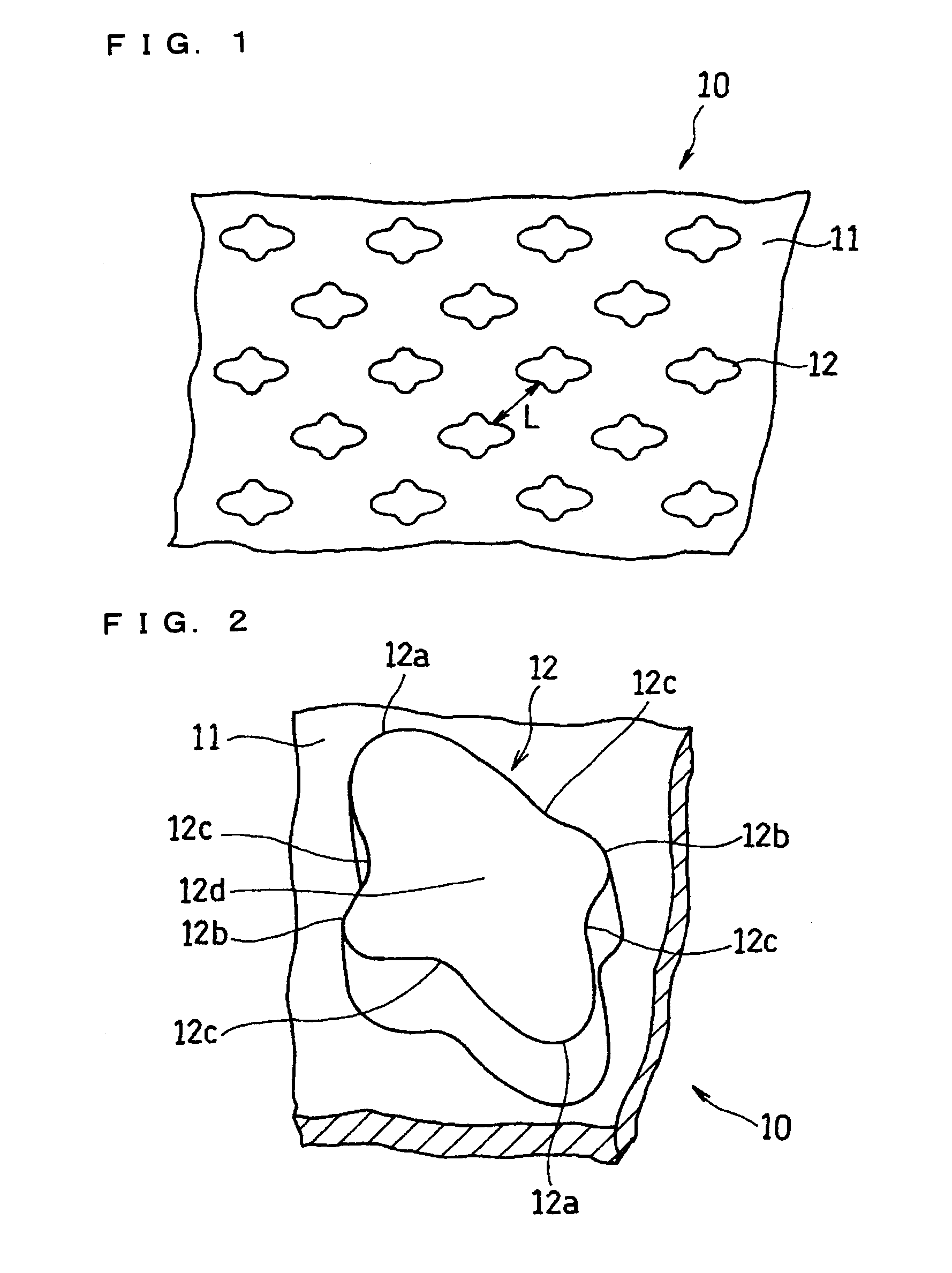
[0112]FIG. 1 is a plan view schematically showing the structure of a current collector for a non-aqueous electrolyte secondary battery according to Embodiment 1 of the invention. FIG. 2 is an enlarged perspective view of a part thereof.

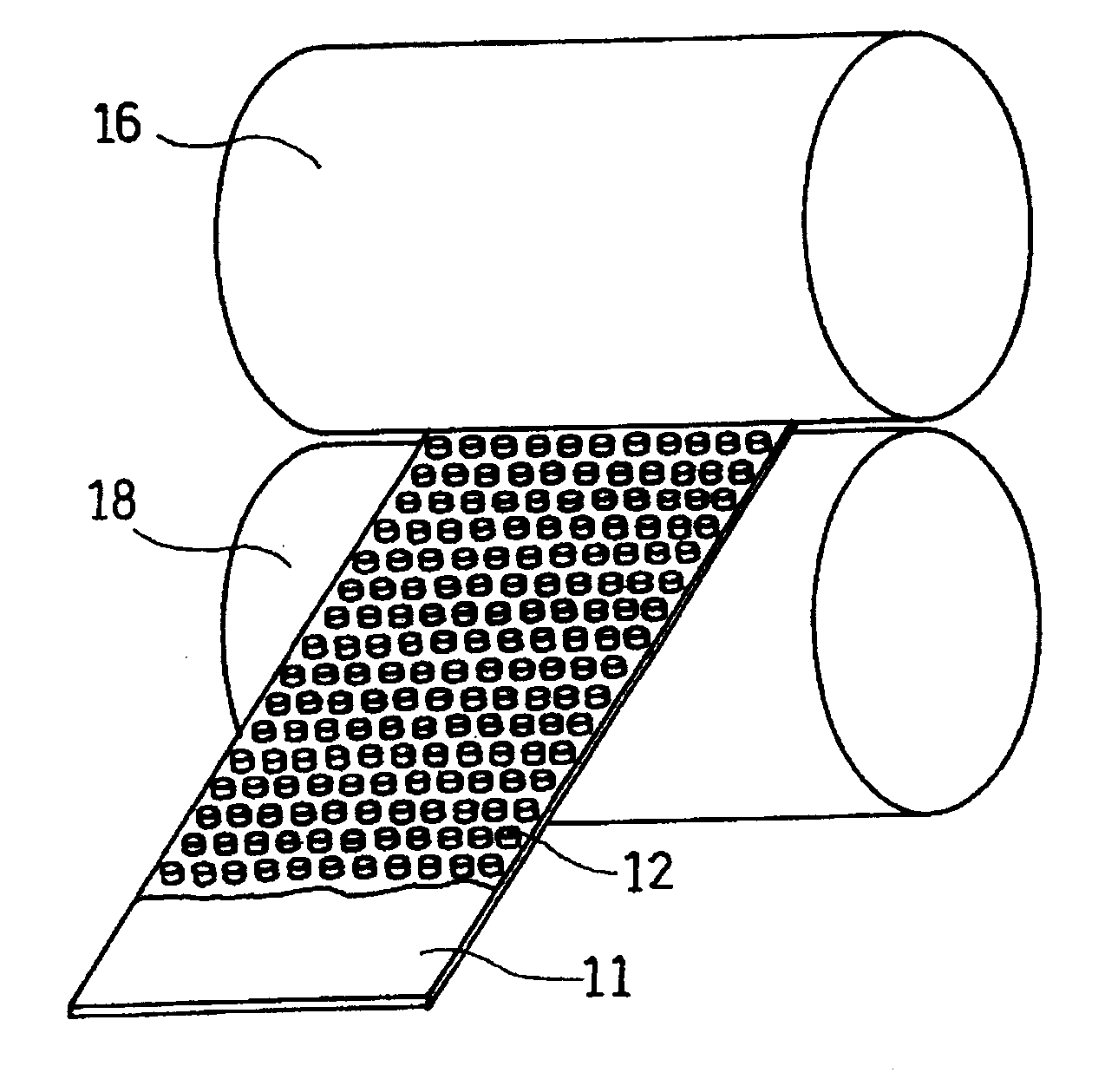
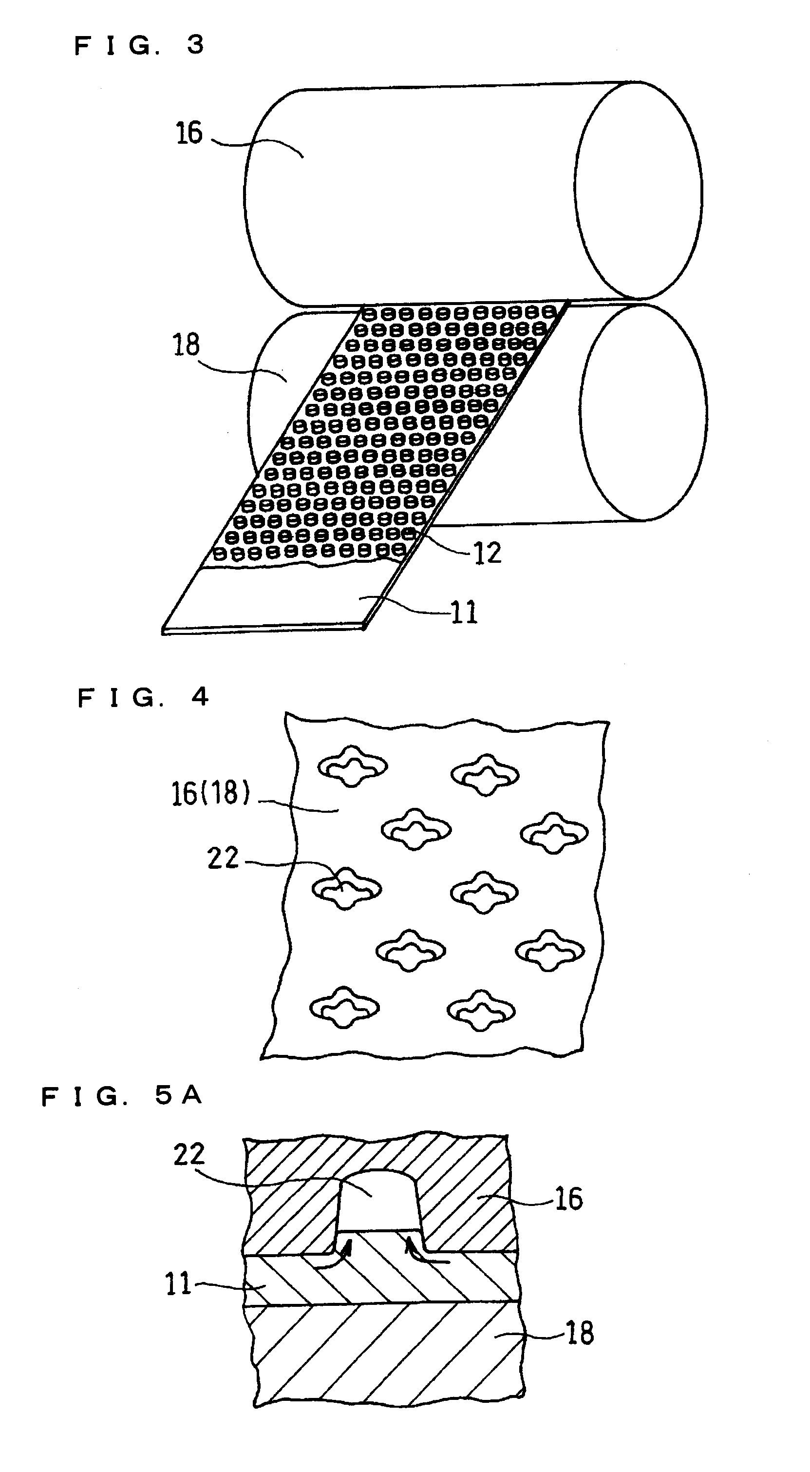
[0113]A current collector 10 illustrated therein includes a metal foil 11 shaped like a long strip and a large number of protrusions 12 formed on at least one face of the metal foil 11 in a predetermined arrangement.

[0114]As illustrated in FIG. 2, the protrusion 12 is substantially rhombic in a plan view. More specifically, when the protrusion 12 is viewed from the direction perpendicular to the surface of the metal foil 11, the protrusion 12 has end portions 12a in the major axis direction (hereinafter referred to as major axis end portions) and end portions 12b in the minor axis direction (hereinafter referred to as minor axis end portions), and these end portions 12a and 12b are curved so as to protrude outward. Also, the protrusion 12 has middle p...

embodiment 2

[0160]Next, Embodiment 2 of the invention is described. FIG. 7 is an enlarged perspective view of a part of a current collector according to Embodiment 2 of the invention.

[0161]A current collector 10A illustrated in FIG. 7 has a protrusion 26, and major axis end portions 26a and minor axis end portions 26b are curved so as to protrude outward, while middle portions 26c between the major axis end portions 26a and the minor axis end portions 26b are curved so as to be recessed inward, just like the current collector 10 illustrated in FIG. 2.

[0162]The current collector 10A of FIG. 7 is different from the current collector 10 of FIG. 2 in that the major axis end portions 26a of the protrusion 26 are higher than the minor axis end portions 26b.

[0163]Between the two major axis end portions 26a is a main top face 26d, which is as high as or higher than the end portions 26a. On both sides of the main top face 26d are sub-top faces 26e, which correspond to the two minor axis end portions 26...

embodiment 3

[0165]Next, Embodiment 3 of the invention is described. FIG. 8 is an enlarged perspective view of a part of a current collector according to Embodiment 3 of the invention.

[0166]A current collector 10B illustrated in FIG. 8 has a protrusion 28, and major axis end portions 28a and minor axis end portions 28b are curved so as to protrude outward, while middle portions 28c between the major axis end portions 28a and the minor axis end portions 28b are curved so as to be recessed inward, just like the current collector 10A illustrated in FIG. 7. Also, the major axis end portions 28a are higher than the minor axis end portions 28b. Between the two major axis end portions 28a is a main top face 28d, which is as high as or higher than the end portions 28a. On both sides of the main top face 26d are sub-top faces 26e, which correspond to the two minor axis end portions 26b, respectively.

[0167]The current collector 10B of FIG. 8 is different from the current collector 10A of FIG. 7 in that th...


PUM

PropertyMeasurementUnit
Fractionaaaaaaaaaa
Lengthaaaaaaaaaa
Heightaaaaaaaaaa

Abstract

A current collector includes a metal foil and protrusions formed on one face or both faces of the metal foil in a predetermined arrangement. The protrusions are substantially rhombic and aligned in a zigzag. Also, both end portions of each protrusion in each of two orthogonal axial directions protrude outward. Middle portions between the end portions are recessed inward. When columnar blocks of an active material are formed on the protrusions to form an active material layer, the gaps between the protrusions can be increased at portions where the interval between the protrusions is the smallest. As a result, internal stress of the active material layer created by charge/discharge of the battery can be alleviated, and the battery life can be increased.

Description

TECHNICAL FIELD[0001]This invention relates to non-aqueous electrolyte secondary batteries represented by lithium ion secondary batteries, and more particularly to a technique for improving the ability of current collectors used therein to hold an active material.BACKGROUND ART[0002]In recent years, lithium ion secondary batteries have been widely used as the power source for portable electronic devices. Lithium ion secondary batteries use a carbonaceous material or the like capable of absorbing and desorbing lithium as a negative electrode active material, while using a composite oxide containing a transition metal and lithium (a lithium-containing transition metal oxide) such as LiCoO2 as a positive electrode active material. This allows lithium ion secondary batteries to have battery characteristics of high voltage and high discharge capacity.[0003]However, with the recent trend of electronic devices and communications devices becoming increasingly more multifunctional, secondary...

Claims


Application Information

Patent Timeline
IPC IPC(8): H01M4/70H01M4/485H01M2/02B21D31/00H01M10/36H01M4/04H01M4/13H01M4/131H01M4/134H01M4/139H01M4/1391H01M4/1395H01M10/052H01M10/0587
CPCH01M4/0404H01M4/131H01M4/1391H01M4/661Y10T29/49108H01M10/052H01M10/0587Y02E60/122Y10T29/49115H01M4/70Y02E60/10Y02P70/50H01M4/02H01M4/04H01M10/05
Inventor BESSHO, KUNIHIKOSUETSUGU, DAISUKEKATO, SEIICHI
Owner PANASONIC CORP
Why Eureka
Try Eureka