Optical probe, drive control method therefor, and endoscope apparatus

Inactive Publication Date: 2011-05-12
FUJIFILM CORP
View PDF8 Cites 25 Cited by
  • Summary
  • Abstract
  • Description
  • Claims
  • Application Information

AI Technical Summary

Benefits of technology

[0035]As has been described above, the present invention has the advantage of the capability to stab

Problems solved by technology

However, when the interior of a body cavity is observed by OCT, the positional relationship between the OCT probe 900 and a body tissue varies during the observation due to beating or pulsation of the body tissue, movement of the hands of an operator, or the like, the above-described feature of OCT cannot be taken advantage of.
1) a part to be observed is away from the center of the

Method used


Image

  • Optical probe, drive control method therefor, and endoscope apparatus
  • Optical probe, drive control method therefor, and endoscope apparatus
  • Optical probe, drive control method therefor, and endoscope apparatus

Examples


Embodiment Construction

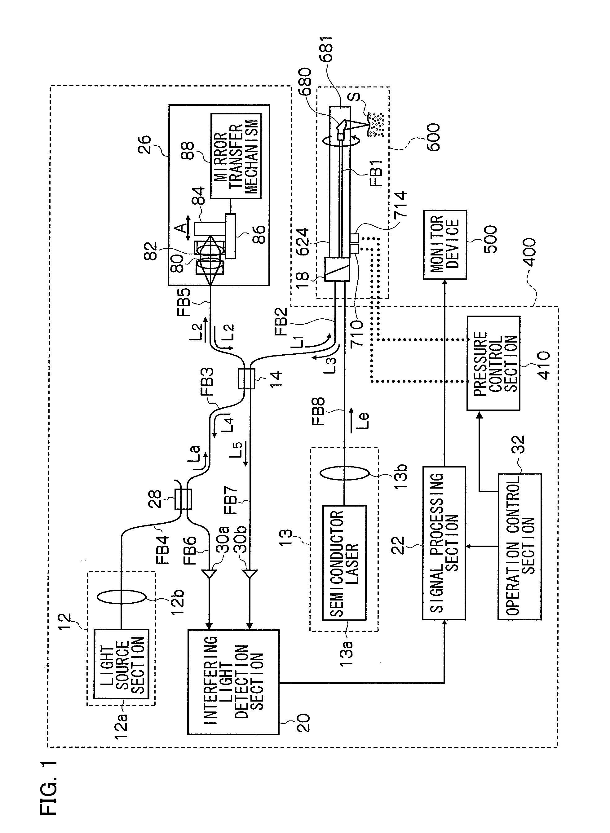
[0050]An embodiment of the present invention will be described in detail below with reference to the accompanying drawings. FIG. 1 is a block diagram showing the internal configurations of an OCT probe and an OCT processor according to the embodiment of the present invention.

[0051]As shown in FIG. 1, an OCT probe 600 and an OCT processor 400 according to this embodiment are intended to acquire an optical tomographic image of an object to be measured by an optical coherence tomography (OCT) measurement method.

[0052]The OCT processor 400 includes a first light source (first light source unit) 12 which emits a light beam La for measurement, an optical fiber coupler (demultiplexing and multiplexing section) 14 which demultiplexes the light beam La emitted from the first light source 12 into a measuring light beam (first rays of light) L1 and a reference light beam L2 and multiplexes a return light beam L3 from an object S to be measured serving as a test object and the reference light b...


PUM


Abstract

An optical probe, comprising:
    • a sheath to be inserted into a body cavity;
    • an optical fiber inside the sheath;
    • an optical component attached to a distal end portion of the optical fiber inside the sheath;
    • wherein a light beam transmitted through the optical fiber is emitted from the optical component toward a body tissue in the body cavity, and
    • wherein the sheath comprises
    • a plurality of balloons spaced at predetermined intervals on a part on the distal end portion side of an outer periphery and capable of inflating/deflating in a radial direction orthogonal to a longitudinal axis,
    • a suction inlet located between the plurality of balloons to draw the body tissue at the part on the distal end portion side of the outer periphery by suction,
    • a balloon inflation port connected to the balloons, and
    • a suction port connected to the suction inlet, and
    • the plurality of balloons are airtightly locked to an body cavity inner wall by supplying a fluid or a gas through the balloon inflation port to pressurize and inflate the balloons, and pressure in a space formed between the plurality of locked balloons and the body cavity inner wall is reduced through the suction port to cause the body tissue to adhere strongly to the part on the distal end portion side of the outer periphery by suction.

Description

BACKGROUND OF THE INVENTION[0001]1. Field of the Invention[0002]The present invention relates to an optical probe for acquiring an optical coherent tomographic image of the interior of a body cavity, a drive control method for the optical probe, and an endoscope apparatus and, more particularly, to an optical probe which stably transmits and receives a measuring light beam in a lumen, a drive control method for the optical probe, and an endoscope apparatus.[0003]2. Description of the Related Art[0004]Conventionally, diagnostic imaging that includes rendering a tomographic image of a living body by inserting an optical probe into a body cavity of a blood vessel, a bile duct, a pancreatic duct, a stomach, an esophagus, or the large intestine and performing radial scanning has been widely performed. As an example, an optical coherent tomography (OCT) apparatus which, when a probe which incorporates an optical fiber having an optical lens and an optical mirror attached to its distal end...

Claims


Application Information

Patent Timeline
IPC IPC(8): A61B1/07A61B6/00
CPCA61B1/00082A61B5/0084A61B5/0066A61B1/00133
Inventor HIROTA, KAZUHIRO
Owner FUJIFILM CORP
Why Eureka
Try Eureka