Spiral type membrane element and spiral type membrane filtering device having the membrane element, and membrane filtering device managing system and membrane filtering device managing method using the device

a filtering device and spiral-type technology, applied in the direction of machines/engines, filtration separation, separation processes, etc., can solve the problems of insufficient management precision, large amount of labor required in specifying work, and inability to say that sufficient optimization is carried out, etc., to achieve suitable maintenance, increase the effect of electric power and high precision

Inactive Publication Date: 2011-05-19
NITTO DENKO CORP
View PDF13 Cites 8 Cited by
  • Summary
  • Abstract
  • Description
  • Claims
  • Application Information

AI Technical Summary

Benefits of technology

[0041]According to the present invention, by performing power generation in the power generating section using the liquid detected by the sensor, a larger amount of electric power can be ensured, and information of the membrane element within the pressure-resistant container (pressure-resistant vessel) can be obtained more easily without performing a cumbersome work. Further, according to the present invention, the cause of change occurring in the spiral type membrane filtering device can be specified more definitely, and a suitable maintenance can be carried out in accordance with the cause, so that the spiral type membrane filtering device can be managed with a higher precision.

Problems solved by technology

However, when the management of processing characteristics is carried out train by train as described above, it is difficult to specify the location of an inconvenience when the inconvenience occurs in the membrane element or the connecting section of only a part of the membrane filtering devices among the numerous membrane filtering devices that are held by a train, thereby raising a problem in that a lot of labor will be required in the specifying work.
However, in the current situation, the optimization is carried out only based on the term of use, so that it is not possible to say that a sufficient optimization is carried out.
However, even in a case in which the management is carried out based on only the data stored in advance in such a wireless tag, the state of each membrane element sometimes changes time by time, so that it is not possible to say that the precision of management is sufficient.

Method used


Image

  • Spiral type membrane element and spiral type membrane filtering device having the membrane element, and membrane filtering device managing system and membrane filtering device managing method using the device
  • Spiral type membrane element and spiral type membrane filtering device having the membrane element, and membrane filtering device managing system and membrane filtering device managing method using the device
  • Spiral type membrane element and spiral type membrane filtering device having the membrane element, and membrane filtering device managing system and membrane filtering device managing method using the device

Examples


first embodiment

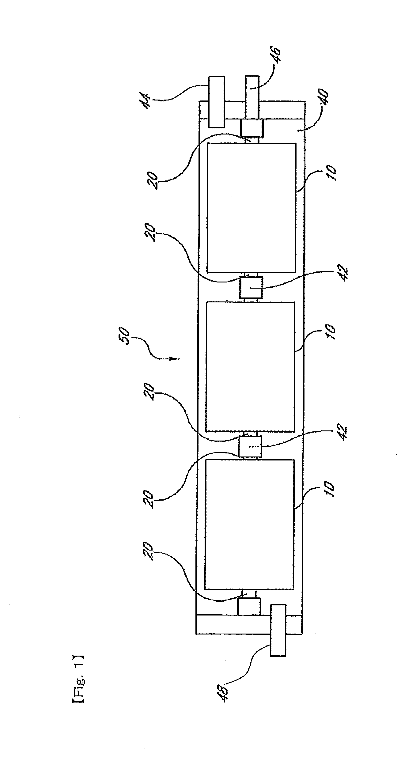
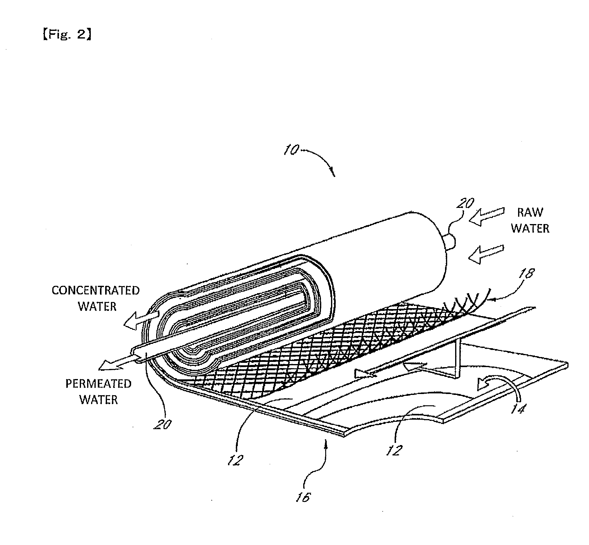
[0084]FIG. 1 is a schematic cross-sectional view illustrating one example of a spiral type membrane filtering device 50 having a spiral type membrane element 10 according to the first embodiment of the present invention. Also, FIG. 2 is a perspective view illustrating an internal construction of a spiral type membrane element 10 of FIG. 1. This spiral type membrane filtering device 50 (hereinafter simply referred to as the “membrane filtering device 50”) is constructed by arranging a plurality of spiral type membrane elements (hereinafter simply referred to as the “membrane elements 10”) in a line within an outer vessel 40.

[0085]The outer vessel 40 is a tube body made of resin, which is referred to as a pressure-resistant vessel, and is formed, for example, with FRP (Fiberglass Reinforced Plastics). A raw water flow inlet 48 through which a raw water (raw liquid) such as waste water or sea water flows in is formed at one end of the outer vessel 40, and the raw water that flows in th...

second embodiment

[0104]In the first embodiment, description has been given on a construction in which power generation is carried out on the basis of the rotation of the rotor (blade wheel 21) disposed in the central pipe 20. In contrast, the second embodiment is different in that the rotor is disposed in the raw water flow path formed by the supply side flow path material 18.

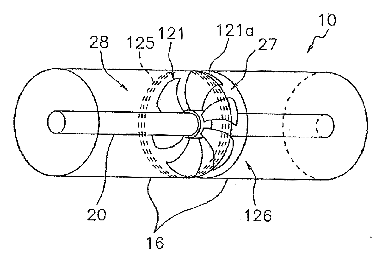
[0105]FIG. 5 is a schematic perspective view illustrating one example of an internal construction of a spiral type membrane element 10 according to the second embodiment of the present invention, showing a state in which the internal construction is seen through. In this example, the membrane member 16 wound around the central pipe 20 is split into two parts along the axial line direction of the central pipe 20, and a space 27 is formed between the end surfaces of these split membrane members 16. This space 27 is a region through which the raw water that flows from the raw water flow path 28 formed by the supply side flow path ...

third embodiment

[0110]In the second embodiment, description has been given on a construction in which power generation is carried out on the basis of the rotation of the rotor (blade wheel 121) disposed in the middle part of the membrane element 10. In contrast, the third embodiment is different in that the rotor is disposed at an end of the membrane element 10.

[0111]FIG. 6 is a schematic perspective view illustrating one example of an internal construction of a spiral type membrane element 10 according to the third embodiment of the present invention, showing a state in which the internal construction is seen through. In this example, an end member 11 functioning as a seal carrier that holds a sealing member (not illustrated) on the outer circumferential surface or a telescope prevention member that prevents the membrane member 16 from being telescopically deformed is mounted on both ends in the axial line direction of the membrane member 16 that is wound around the central pipe 20. The raw water ...


PUM

PropertyMeasurementUnit
diameteraaaaaaaaaa
electric poweraaaaaaaaaa
pressureaaaaaaaaaa

Abstract

Provided are a spiral type membrane element that can ensure a larger amount of electric power without performing a cumbersome work and a spiral type membrane filtering device having the element, as well as a membrane filtering device managing system and a membrane filtering device managing method using the device. The spiral type membrane element comprises a sensor for detecting a property of liquid, a power generating section that generates electric power by using said liquid, and a wireless transmitting section that receives the electric power supplied from said power generating section and wirelessly transmits a detection signal from said sensor. By generating electric power in the power generating section with use of the liquid detected by the sensor, a larger amount of electric power can be ensured without performing a cumbersome work.

Description

TECHNICAL FIELD[0001]The present invention relates to a spiral type membrane element in which a separation membrane, a supply side flow path material, and a permeation side flow path material in a laminated state are wound in a spiral form around a central pipe, and a permeated liquid that is filtered by the separation membrane from a raw liquid supplied via a raw liquid flow path formed by the supply side flow path material is guided to the central pipe via the permeation side flow path material, and a spiral type membrane filtering device having the element, as well as a membrane filtering device managing system and a membrane filtering device managing method using the device.BACKGROUND ART[0002]A spiral type membrane filtering device (hereinafter simply referred to as the “membrane filtering device” is known that is constructed by plurally arranging the aforesaid spiral type membrane element (hereinafter simply referred to as the “membrane element”) in a line and connecting betwe...

Claims


Application Information

Patent Timeline
Patent Type & Authority Applications(United States)
IPC IPC(8): B01D63/10B01D63/12
CPCB01D61/12B01D61/22B01D63/10F05B2250/25B01D65/10F03B13/00F05B2220/20B01D63/12
Inventor KONISHI, TAKAHISAMARUYAMA, KOUJIKOUNO, TOSHIKIHIRANO, KEISUKEOOTANI, AKIRAYOSHIKAWA, HIROSHIIKEYAMA, NORIO
Owner NITTO DENKO CORP
Why Eureka
Try Eureka