Transmit/receive coil for ultra-high field MRI

a transmission coil and ultra-high field technology, applied in the field of magnetic resonance imaging and spectroscopy, can solve the problems of low magnetic field, relatively lower spatial resolution, and lower signal strength and correspondingly lower signal-to-noise ratio (snr), so as to improve the correspondence between the transmit and the receiver, improve the effect of magnetic resonance and improve performan

Active Publication Date: 2011-05-19
KONINKLIJKE PHILIPS ELECTRONICS NV
View PDF28 Cites 5 Cited by
  • Summary
  • Abstract
  • Description
  • Claims
  • Application Information

AI Technical Summary

Benefits of technology

[0008]One advantage resides in improved correspondence between the transmit and receive sensitivity regions.
[0009]Another advantage resides in improved magnetic resonance at high magnetic field.
[0010]Another advantage resides in magnetic resonance coils with improved performance at high magnetic field.
[0011]Another advantage resides in better targeting of magnetic resonance excitation and signal reception.

Problems solved by technology

However, low magnetic field has certain disadvantages with acquisition time constraints in mind, such as relatively lower spatial resolution, lower signal strength and correspondingly lower signal-to-noise ratio (SNR), and so forth.
At high magnetic field, for example at 7 Tesla, the magnetic resonance frequency is substantially higher (in proportion to the main field), the corresponding radio frequency (RF) wavelength is substantially shorter, and tissue properties and object shape (load) can lead to substantial B1 non-uniformity on the scale of a typical human head or extremity such as calf.
At higher fields like 7 T, the region of sensitivity may exhibit substantial load-induced non-uniformity and asymmetry, even for a uniform object.
Even worse, the transmit and receive sensitivity patterns are different spatially.

Method used


Image

  • Transmit/receive coil for ultra-high field MRI
  • Transmit/receive coil for ultra-high field MRI
  • Transmit/receive coil for ultra-high field MRI

Examples


Embodiment Construction

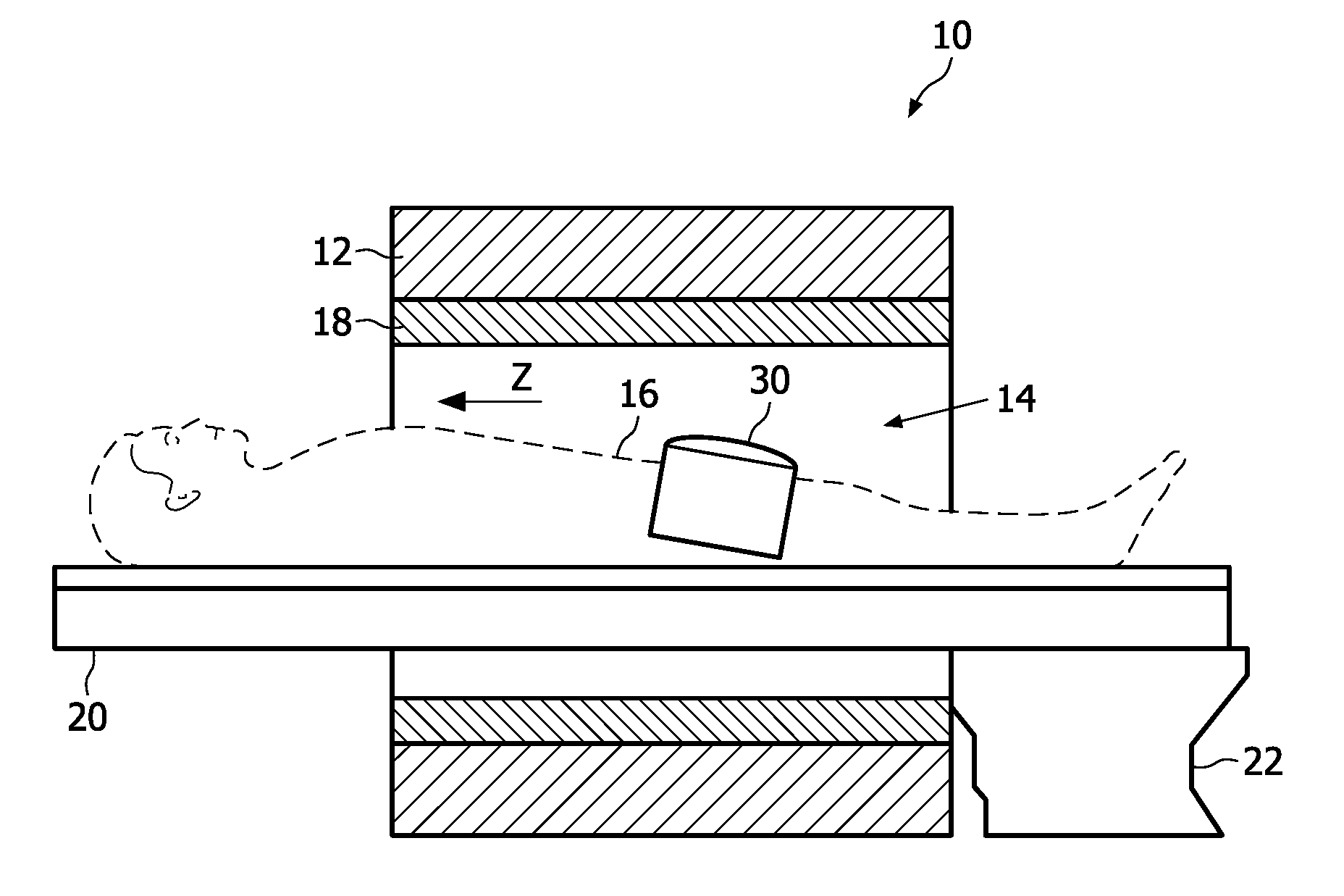
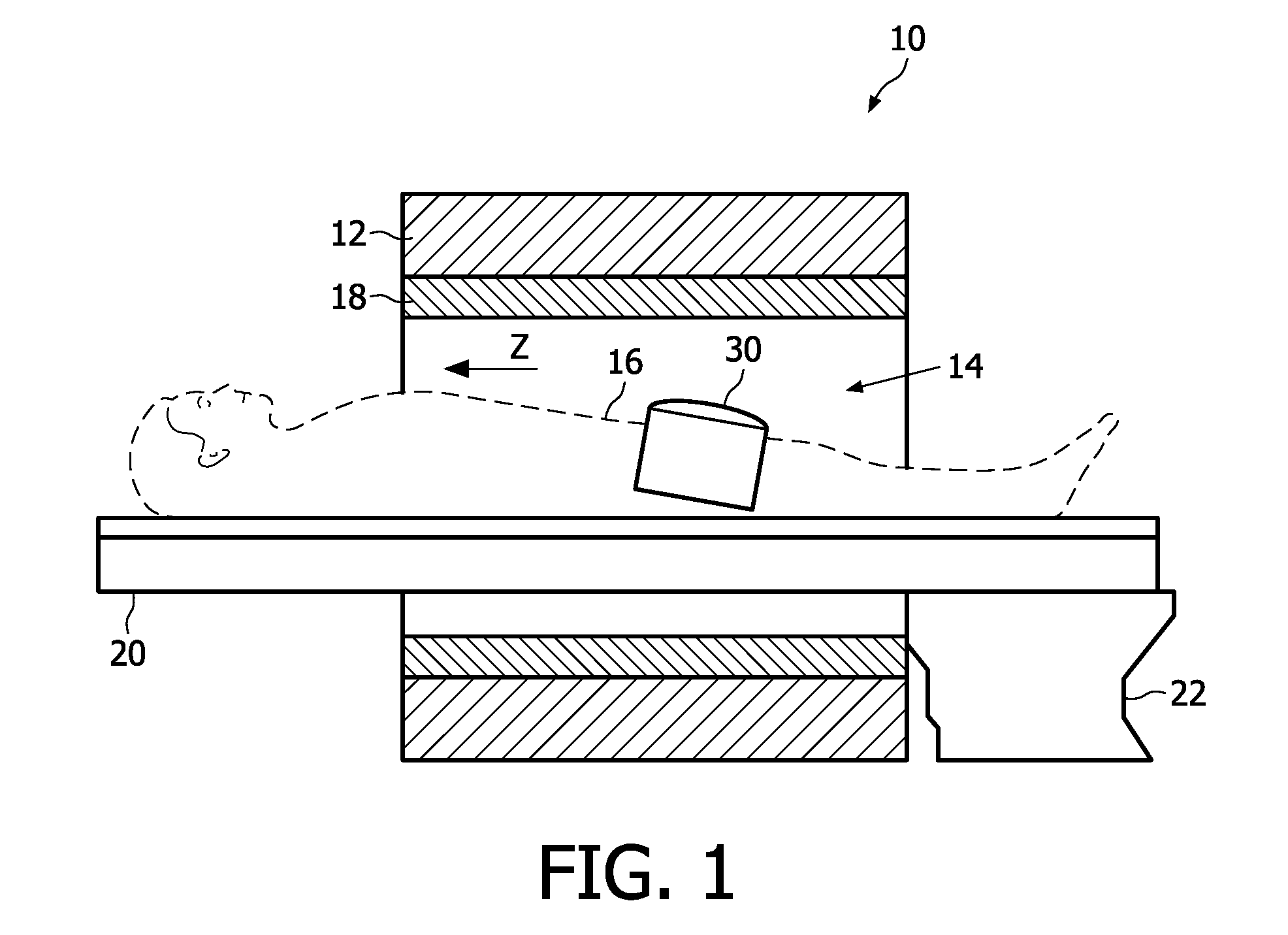
[0021]With reference to FIG. 1, a magnetic resonance scanner 10 includes a main magnet 12 generating a static (B0) magnetic field having a field direction oriented parallel or anti-parallel with an axial or “z” direction (indicated in FIG. 1) in an examination region 14 in which is disposed a subject 16 (shown in dashed line in FIG. 1). The illustrated magnetic resonance scanner 10 is a horizontal bore-type scanner shown in cross-section to reveal selected components; however, other types of magnetic resonance scanners can be used. The magnetic resonance scanner 10 is a high-field scanner in which the main magnet 12 produces the static main magnetic field (also known as B0 magnetic field) in the examination region 14 at a magnetic field strength greater than 3 Tesla, and in some embodiments greater than or about 5 Tesla. In some embodiments, the main magnet 12 produces a static (B0) magnetic field in the examination region 14 at a magnetic field strength of 7 Tesla. Higher magnetic ...


PUM


Abstract

A magnetic resonance coil comprises a first set of coil elements (54, 56, 80) operatively connectable with a transmit channel (66, 74) to couple with a transmit region of sensitivity for a selected load at a magnetic field strength greater than 3 Tesla, and a second set of coil elements (52, 54, 82) operatively connectable with a receive channel (66, 74) to couple with a receive region of sensitivity for the selected load at the magnetic field strength greater than 3 Tesla. The first set of coil elements is arranged proximate to but not surrounding the transmit region of sensitivity, and the second set of coil elements is arranged proximate to but not surrounding the receive region of sensitivity. The first set of coil elements and the second set of coil elements having at least one coil element (52, 56) not in common. The first and second sets of coil elements define transmit and receive regions of sensitivity for the selected load at the magnetic field strength greater than 3 Tesla that are substantially similar.

Description

FIELD OF THE INVENTION[0001]The following relates to the magnetic resonance arts. The following finds illustrative application to magnetic resonance imaging and spectroscopy, and is described with particular reference thereto. However, the following will find application in other magnetic resonance and radio frequency applications.BACKGROUND[0002]At low magnetic field, for example at 1.5 Tesla, the magnetic resonance frequency is relatively low, resulting in a corresponding radio frequency (RF) wavelength that is relatively long compared to the size of the object. As a result, a low magnetic field tends to provide good spatial uniformity on the scale of a typical human anatomical region of interest (e.g., head, torso, limb, or so forth). Accordingly, those skilled in the art have typically employed a volume coil such as a birdcage coil for magnetic resonance excitation, and have used a volume coil or a local coil (possibly comprising a plurality of coil elements) for magnetic resona...

Claims


Application Information

Patent Timeline
Patent Type & Authority Applications(United States)
IPC IPC(8): G01R33/44
CPCG01R33/5659G01R33/3415
Inventor ZHAI, ZHIYONGGAUSS, ROBERTWONG, EDDY YU PINGMORICH, MICHAEL A.NIEMAN, KEVIN M.DEMEESTER, GORDON D.
Owner KONINKLIJKE PHILIPS ELECTRONICS NV
Why Eureka
Try Eureka