Liquid crystal display device

a liquid crystal display and display device technology, applied in the field of liquid crystal display devices, can solve the problems of insufficient effect of reducing power consumption, difficulty in further improving efficiency, and difficulty in sufficiently improving diffraction efficiency, so as to improve light utilization efficiency, improve efficiency, and reduce power consumption.

Inactive Publication Date: 2011-05-19
PANASONIC CORP
View PDF2 Cites 37 Cited by
  • Summary
  • Abstract
  • Description
  • Claims
  • Application Information

AI Technical Summary

Benefits of technology

[0022]Thus, an object of this invention is to provide a low power consumption and high quality liquid crystal display device capable of improving the light utilization efficiency more than a conventional configuration and realizing a high quality picture.

Problems solved by technology

Nevertheless, since the power consumption is increasing pursuant to the enlargement of the liquid crystal display device, the development of technology capable of realizing low power consumption is being demanded.
Nevertheless, with the foregoing conventional configurations, no specific configuration has been presented for reducing power consumption, or the effect of reducing power consumption is insufficient.
Specifically, Patent Documents 1 to 3 describe a configuration of performing wavelength separation using diffraction and guiding light to the respective sub-pixels of the liquid crystal panel, but Patent Documents 1 to 3 are all unable to sufficiently improve the light utilization efficiency, and further improvement in efficiency is difficult.
With this kind of configuration, it is difficult to sufficiently improve the diffraction efficiency.
However, since the incidence angle to the volume hologram will be limited, the output efficiency of light that entered the light guide plate will deteriorate.
Moreover, although Patent Document 4 shows a configuration of forming a mirror for performing wavelength separation inside the light guide plate, it is difficult to manufacture a light guide plate having this kind of structure, and there is concern that costs will increase.
Moreover, the color filter described in Patent Document 5 is merely used in substitute for a conventional absorptive color filter, and Patent Document 5 fails to show a configuration of effectively using the reflected light.
Nevertheless, the effect of this polarization color filter is insufficient when used as a substitute for the polarizing plate and color filter of the liquid crystal panel, and, even though the light utilization efficiency can be improved to a certain degree, the picture quality will deteriorate.
Moreover, with the polarization color filter of Patent Document 7, transmittance of the unwanted polarization component is 60% or more of the required polarization component, and the contrast will deteriorate since the extinction ratio of light that is guided to the pixels of the liquid crystal panel is inferior.

Method used


Image

  • Liquid crystal display device
  • Liquid crystal display device
  • Liquid crystal display device

Examples


first embodiment

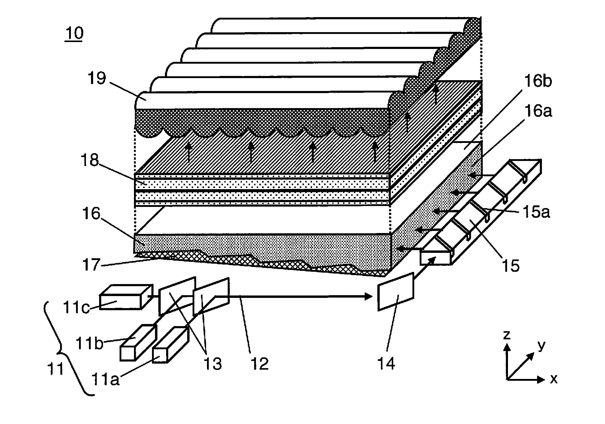
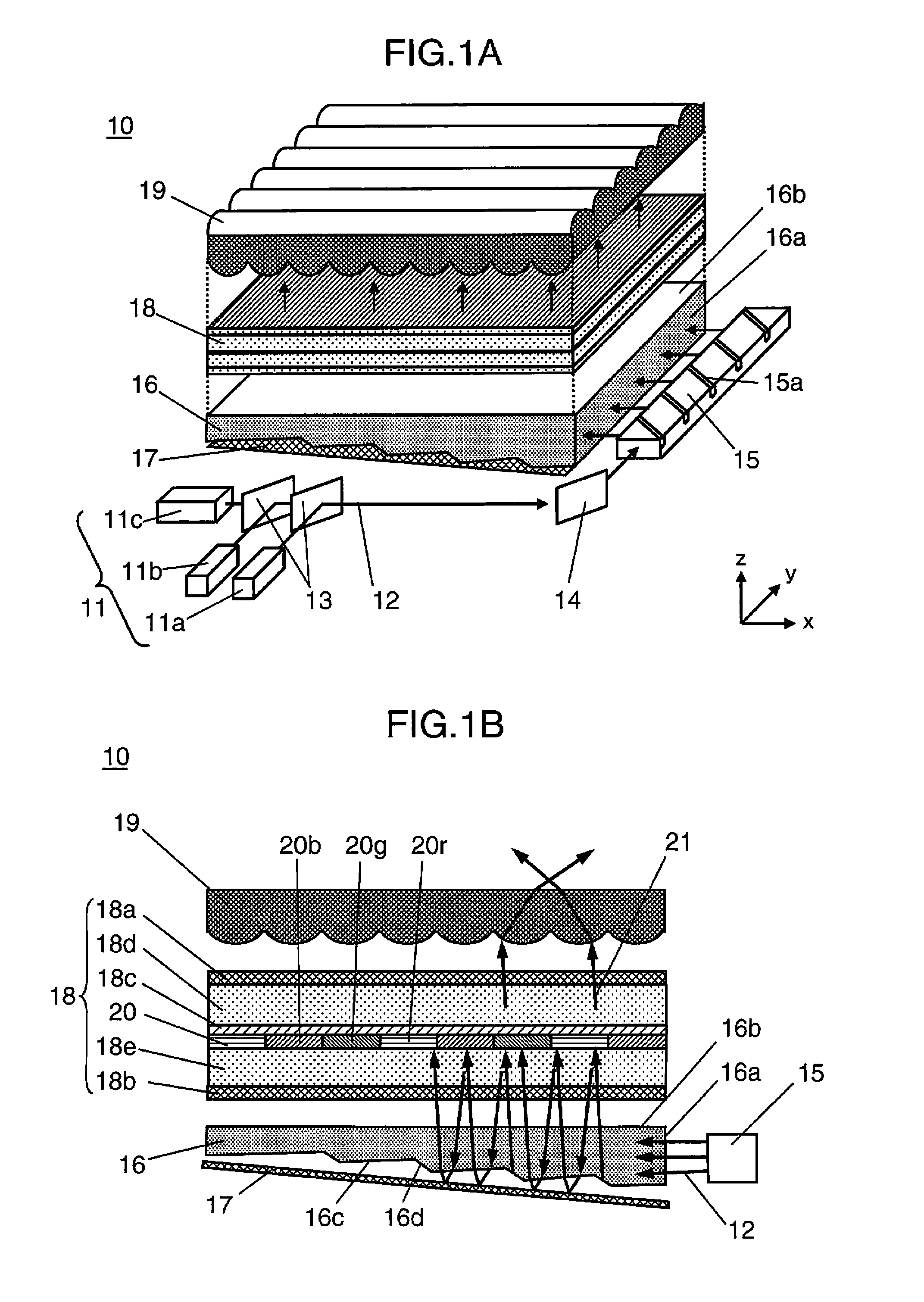
[0053]FIG. 1A and FIG. 1B are diagrams showing the schematic configuration of the liquid crystal display device according to the first embodiment of the present invention. FIG. 1A is a perspective view schematically showing the overall configuration of the liquid crystal display device, and FIG. 1B shows a cross section of the xz in-plane of the essential part in FIG. 1A. Note that, in FIG. 1A and FIG. 1B, for the ease of understanding of the configuration of the respective parts of the liquid crystal display device, the respective parts are shown to be disposed in isolation. However, in the actual configuration, the respective parts are integrally fixed by being mounted on a base plate or within a frame not shown.

[0054]As shown in FIG. 1A and FIG. 1B, the liquid crystal display device 10 according to this embodiment comprises a laser light source 11 configured from three light sources; namely, red laser light source (hereinafter referred to as the “R light source”) 11a for outputti...

second embodiment

[0113]FIG. 6A and FIG. 6B are schematic configuration diagrams showing the liquid crystal display device 40 according to the second embodiment of the present invention, wherein FIG. 6A is a cross section of the essential part of the liquid crystal display device 40, and FIG. 6B shows an enlarged view of the wire grid polarizing plate 41 in FIG. 6A.

[0114]The configuration of FIG. 6A differs from the configuration of FIG. 4 only in that the polarizing plate on the backlight unit side of the liquid crystal panel 18 is eliminated and that a wire grid polarizing plate 41 (polarization separation part) is disposed in substitute for the reflective sheet. Since the other constituent elements are the same, these are given the same reference numeral and the explanation thereof is omitted. However, the polarization direction of the laser beam 12 (illuminating light) that enters the light guide plate 16 and the liquid crystal panel 18 is different from the first embodiment, and is configured to...

third embodiment

[0140]FIG. 9A and FIG. 9B are schematic configuration diagrams showing the liquid crystal display device according to the third embodiment of the present invention, wherein FIG. 9A is a cross section of the essential part of the liquid crystal display device 60, and FIG. 9B is a schematic diagram showing the film structure of the reflective color filter 61 in FIG. 9A.

[0141]The configuration of FIG. 9A differs from the configuration of FIG. 1A only in that the polarizing plate on the backlight unit side of the liquid crystal panel 18 is eliminated and the polarization element 24 is disposed adjacent to the side surface 16a of the light guide plate 16, and the structure of the reflective color filter has been changed. Since the other constituent elements are the same, these are given the same reference numeral and the explanation thereof is omitted. Note that the polarization direction of the laser beam 12 that enters the light guide plate 16 and the liquid crystal panel 18 is differe...


PUM

PropertyMeasurementUnit
transmittanceaaaaaaaaaa

Abstract

A liquid crystal display device has: a light source, a light guide plate for causing light from the light source to enter from a side surface of the light guide plate and exit as illuminating light from one principal surface thereof; a liquid crystal panel which includes a reflective color filter having wavelength selectivity in transmittance and reflectance and a polarizing plate disposed on a side that is closer to the light guide plate than the reflective color filter, and which is disposed on a light path of the illuminating light; and a recycle part for reflecting the illuminating light that has been reflected by the reflective color filter toward the reflective color filter once again, wherein the light from the light source is configured to enter the light guide plate as approximately linear polarization, and the polarizing plate of the liquid crystal panel is configured so exhibit transmittance of 90% or higher.

Description

TECHNICAL FIELD[0001]The present invention relates to a liquid crystal display device with high light utilization efficiency. More specifically, the present invention relates to a liquid crystal display device capable of efficiently guiding light having a predetermined wavelength to the respective sub-pixels of the liquid crystal panel.BACKGROUND ART[0002]A liquid crystal display device is a system of displaying images by using the electro-optic effect based on the orientation of the liquid crystal molecules, and controlling the amount of transmission of the light that is irradiated from the back surface, and generally speaking a planar illuminating device referred to as a backlight unit configured from a cold-cathode tube or the like is required. In recent years, this kind of liquid crystal display device is being manufactured as larger screens, and liquid crystal display devices for TV use of 50-inch sizes and larger have been put into practical use. Nevertheless, since the power ...

Claims


Application Information

Patent Timeline
Patent Type & Authority Applications(United States)
IPC IPC(8): G02F1/1335
CPCG02B6/0028G02B6/0038G02B6/0048G02B6/005G02B6/0056G02F2001/133567G02F1/133615G02F1/13362G02F1/133621G02F2001/133521G02F1/133514G02F1/133521G02F1/133567
Inventor NAGATA, TAKAYUKIFURUYA, HIROYUKIITOH, TATSUO
Owner PANASONIC CORP
Why Eureka
Try Eureka