Switching controller having switching frequency hopping for power converter

Inactive Publication Date: 2011-05-19
FAIRCHILD TAIWAN
View PDF4 Cites 17 Cited by
  • Summary
  • Abstract
  • Description
  • Claims
  • Application Information

AI Technical Summary

Benefits of technology

[0006]The present invention provides a switching controller having switching frequency hopping to reduce the EMI for a power converter. The switching controller includes a first oscillator to generate a pulse signal and a maximum duty-cycle signal for determining a switching frequency of a switching signal. A maximum duty-cycle circuit generates a maximum duty-cycle signal in response to the switching signal for determining the switching frequency of the switching signal. A pattern generator with a second oscillator generates a digital pattern code in response to a clock signal, wherein the clock

Problems solved by technology

A problem of utilizing pulse width modulation is that the power converters operate at a relatively high frequency compared to the frequency of the AC power source, which results in a high frequency signal generated by the power converters.
Although the switching

Method used


Image

  • Switching controller having switching frequency hopping for power converter
  • Switching controller having switching frequency hopping for power converter
  • Switching controller having switching frequency hopping for power converter

Examples


first embodiment

[0015]FIG. 1 shows a power supply having a switching controller according to a first embodiment of the present invention. The switching controller includes a PWM circuit and a frequency modulator 10. The switching controller generates a switching signal VPWM for switching a transformer T1 via a power transistor Q1. The transformer T1 receives input voltage Vin and generates an output voltage Vo having a primary side Np and a secondary side Ns. The duty cycle of the switching signal VPWM determines the power supplied by an AC power source to an output of the power supply. The PWM circuit comprises an inverter 20, a comparator 30, a first AND gate 40, a D flip-flop 50, and a second AND gate 60. A switching current IP of the transformer T1 is converted to a current signal VS (in voltage form) through a sense resistor RS. The current signal VS is provided to the PWM circuit for pulse width modulation of the switching signal VPWM. A negative input of the comparator 30 is supplied with th...

second embodiment

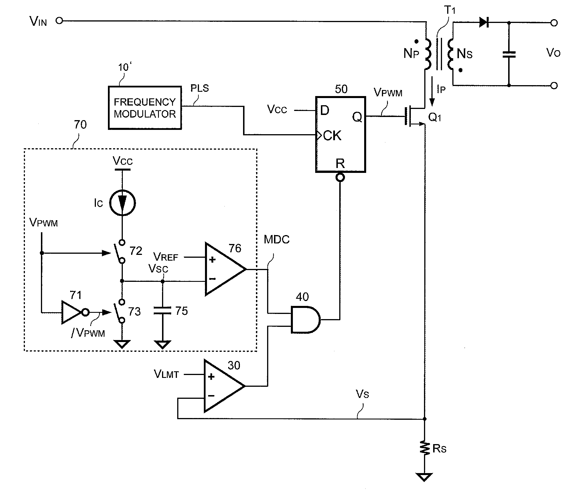
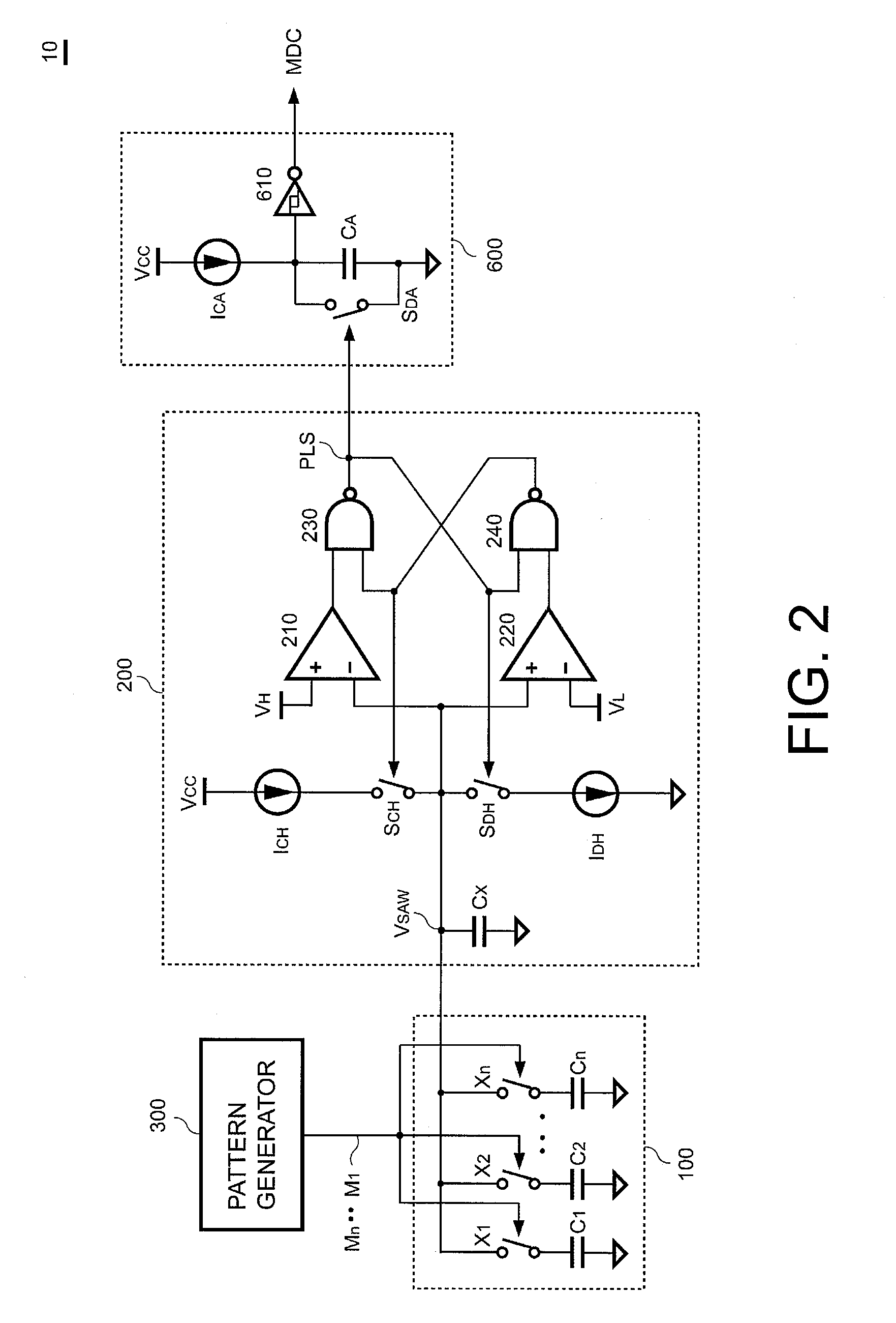
[0026]FIG. 5 shows a power supply having a switching controller according to a second embodiment of the present invention. FIG. 6 shows a frequency modulator having frequency hopping according to the second embodiment of the present invention. Referring to FIG. 5 and FIG. 6, the design concept of the switching controller of the second embodiment is similar to that of the first embodiment, and the difference therebetween is described as follows.

[0027]The switching controller of the second embodiment includes a PWM circuit, a frequency modulator 10′, and a maximum duty-cycle circuit 70 as shown in FIG. 5. The PWM circuit generates the switching signal VPWM in accordance with the pulse signal PLS and the maximum duty-cycle signal MDC. For design purpose, some elements such as the inverter 20 and the second AND gate 60 in FIG. 1 are omitted to simplify the architecture of the PWM circuit in the present embodiment. However, the operation of the PWM circuit of the second embodiment is sim...


PUM


Abstract

A switching controller having switching frequency hopping for a power converter includes an oscillator generating a pulse signal for determining a switching frequency of a switching signal, a maximum duty-cycle circuit generating a maximum duty-cycle signal in response to the switching signal for determining the switching frequency of the switching signal, a pattern generator generating a digital pattern code in response to a clock signal, a programmable capacitor coupled to the pattern generator and the oscillator for modulating the switching frequency of the switching signal in response to the digital pattern code, and a PWM circuit coupled to the oscillator and the maximum duty-cycle circuit for generating the switching signal in accordance with the pulse signal and the maximum duty-cycle signal. A maximum on-time of the switching signal is limited by the maximum duty-cycle signal. The switching signal is utilized to switch a transformer of the power converter.

Description

CROSS-REFERENCE TO RELATED APPLICATION[0001]This is a continuation-in-part application of and claims the priority benefit of patent application Ser. No. 12 / 276,415, filed on Nov. 24, 2008, which claims the priority benefit of U.S. provisional application Ser. No. 61 / 188,060, filed on Aug. 5, 2008. The entirety of each of the above-mentioned patent applications is hereby incorporated by reference herein and made a part of this specification.BACKGROUND OF THE INVENTION[0002]1. Field of the Invention[0003]The present invention relates to a power converter in a switching mode, and more specifically relates to a switching controller with switching frequency hopping.[0004]2. Description of Related Art[0005]Power converters have been used to convert an AC power source to a regulated voltage or current. The power converters need to maintain an output voltage, output a current, or output power within a regulated range for efficient and safe operation of an electronic device. A problem of uti...

Claims


Application Information

Patent Timeline
IPC IPC(8): H02M3/335
CPCH02M3/33507H02M1/44
Inventor HUANG, WEI-HSUANLIN, JENN-YU G.YANG, TA-YUNG
Owner FAIRCHILD TAIWAN
Why Eureka
Try Eureka