
Wireless communication system, transmitter and receiver

a communication system and transmitter technology, applied in the field of wireless communication technology, can solve the problems of high papr (peak to average power ratio), extremely large trouble in uplink where amplifiers have limitations, etc., and achieve the effect of improving throughput, increasing frequency selectivity, and reducing the error rate of signals

Inactive Publication Date: 2011-05-19
SHARP KK
View PDF18 Cites 22 Cited by
  • Summary
  • Abstract
  • Description
  • Claims
  • Application Information

AI Technical Summary

Benefits of technology

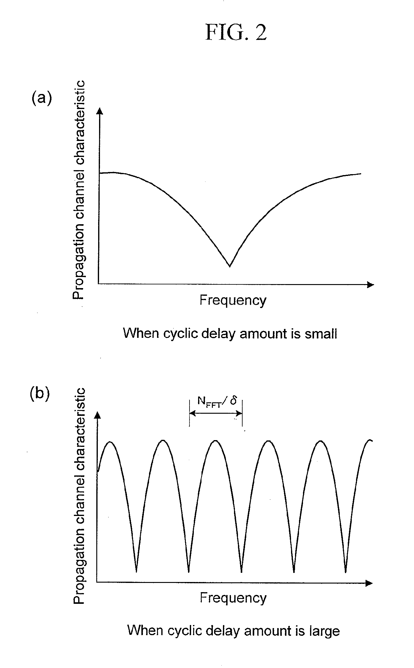
The present invention relates to a wireless communication technique for obtaining a frequency diversity effect using multiple transmission antennas to improve the efficiency of a limited frequency band. The invention proposes a technique for achieving a low peak-to-average power ratio (PAPR) in uplink, which is important for achieving a high use efficiency of frequency resources in a wireless communication system. The invention also proposes a cyclic delay diversity (CDD) technique for improving the error rate of a received signal by increasing the frequency selectivity of a propagation channel. The CDD technique involves delaying signals from transmission antennas and adding the number of multipaths in the propagation channel, which can enhance the frequency selectivity of the channel. Overall, the invention provides a solution for achieving a low PAPR and improving the error rate of a received signal in a wireless communication system.

Problems solved by technology

However, use of such a multi-carrier transmission scheme has a problem of making PAPR (Peak to Average Power Ratio) high although achieving very high use of frequency.
This problem with the PAPR does not cause a large trouble in downlink where there is a margin in a transmission power amplification function, but causes an extremely large trouble in uplink where amplifiers have limitations.

Method used


Image

  • Wireless communication system, transmitter and receiver
  • Wireless communication system, transmitter and receiver
  • Wireless communication system, transmitter and receiver

Examples


first embodiment

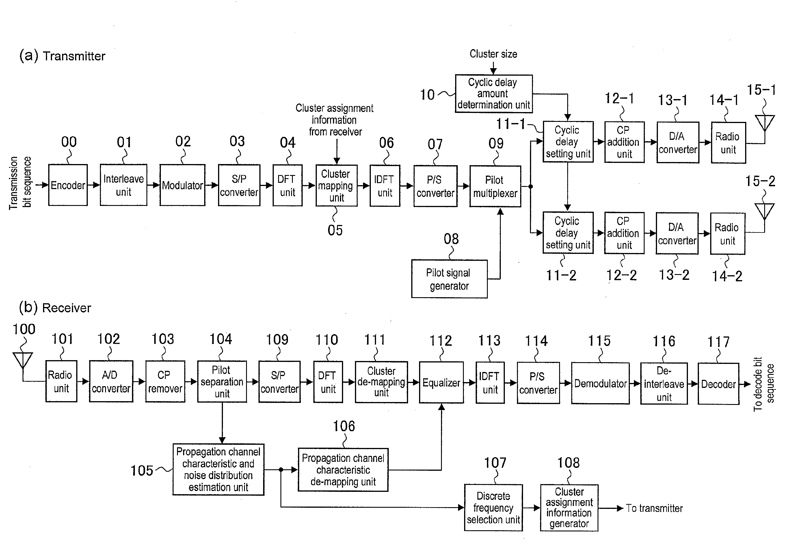
[0031]In a first embodiment of the present invention, a description will be given of a technique using a method for setting an appropriate CDD delay amount when a cluster size (the number of subcarriers to be included in a single cluster) is determined. Here, the description will be given of an example using two transmission antennas for the sake of simplicity of the description. In addition, the cluster size will be described on the assumption that an appropriate value of the cluster size is already determined between a transmitter and a receiver will be described.

[0032]Normally, the cluster size is determined on the basis of a difference between a characteristic of a power amplifier and a transmission power (referred to as a “power headroom” or the like in some cases) in a transmitter. The PAPR property becomes worse as the cluster size is set smaller. Conversely, the PAPR property becomes closer to a PAPR property of a single carrier scheme as the cluster size is set larger. Acco...

second embodiment

[0044]Next, a communication technique according to a second embodiment of the present invention will be described with reference to the drawings. The communication technique according to this embodiment assumes a case where a temporal propagation channel fluctuation occurs drastically, such as a case where a terminal device moves fast. In this case, even if a propagation channel estimation is made by the receiver and then is fed back to the transmitter, the propagation channel characteristic is likely to change when the transmission using the information is performed. As a result, the cluster assignment performed with the propagation characteristic taken into consideration is not effective in this case.

[0045]In this respect, frequency diversity that is high on average no matter which band the assignment is performed on regardless of the propagation channel characteristic is preferred in a situation where a terminal device moves fast.

[0046]Here, with reference to FIG. 3, a descriptio...

third embodiment

[0050]The first and second embodiments are shown as the case where the number of transmission antennas is determined to be two. In this embodiment, however, an example in which N (>2) transmission antennas are used will be described. To begin with, consideration is given to a case where, as described in the first embodiment, a cyclic delay amount is set such that a cluster is assigned to only a frequency having a good characteristic with the cluster size matched with the cycle of the frequency selectivity of the propagation channel characteristic.

[0051]Frequency rotation φi(n) given by the n-th (1

[Equation4]φi(n)=exp(-j·2πNFFT·δn·i)(4)

[0052]δn is a value determined for each antenna. A condition required for δn is that the fluctuation cycle of the frequency response of the propagation channel expected to occur in the receiver is at least twice the cluster size (the value is set to be twice the cluster size in the first embodiment). A...


PUM


Abstract

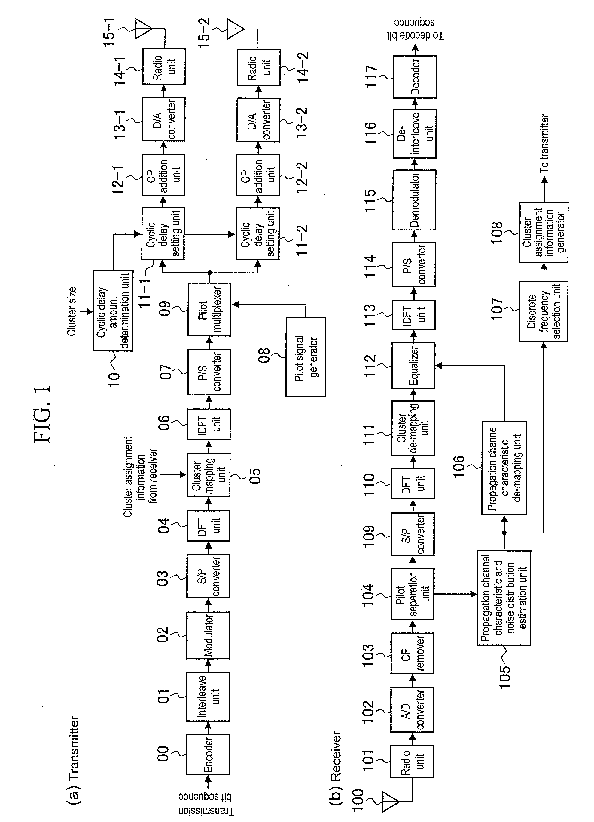
According to the present invention, a transmitter includes: multiple antennas 15-1, 15-2; a DFT unit 04 configured to transform a time domain signal into a frequency domain signal; a cluster mapping unit 05 configured to divide the frequency domain signal into clusters and to assign the clusters to frequencies on the basis of cluster assignment information; an IDFT unit 06 configured to transform a mapped frequency domain signal into a time domain signal; and cyclic delay setting units 11-1, 11-2 configured to set, for the respective multiple antennas, a cyclic delay amount to the IDFT-transformed time domain signal.

Description

TECHNICAL FIELD[0001]The present invention relates to a wireless communication technique, and particularly to a communication technique for obtaining a frequency diversity effect by use of multiple transmission antennas.BACKGROUND ART[0002]In recent years, a high-speed and large-capacity data transmission has been demanded in a wireless communication system. Thus, research for increasing the use efficiency of a limited frequency band has been actively conducted. As a technique for achieving the purpose, high-speed communications using a multi-carrier transmission scheme such as an OFDM (Orthogonal Frequency Division Multiplex) scheme can be cited. However, use of such a multi-carrier transmission scheme has a problem of making PAPR (Peak to Average Power Ratio) high although achieving very high use of frequency.[0003]This problem with the PAPR does not cause a large trouble in downlink where there is a margin in a transmission power amplification function, but causes an extremely la...

Claims


Application Information

Patent Timeline
Patent Type & Authority Applications(United States)
IPC IPC(8): H04B7/02H04L27/00
CPCH04B7/0671H04L27/2636H04L27/2614
Inventor TAKAHASHI, HIROKIHAMAGUCHI, YASUHIROYOKOMAKURA, KAZUNARINAKAMURA, OSAMUGOTO, JUNGO
Owner SHARP KK
Learn More