

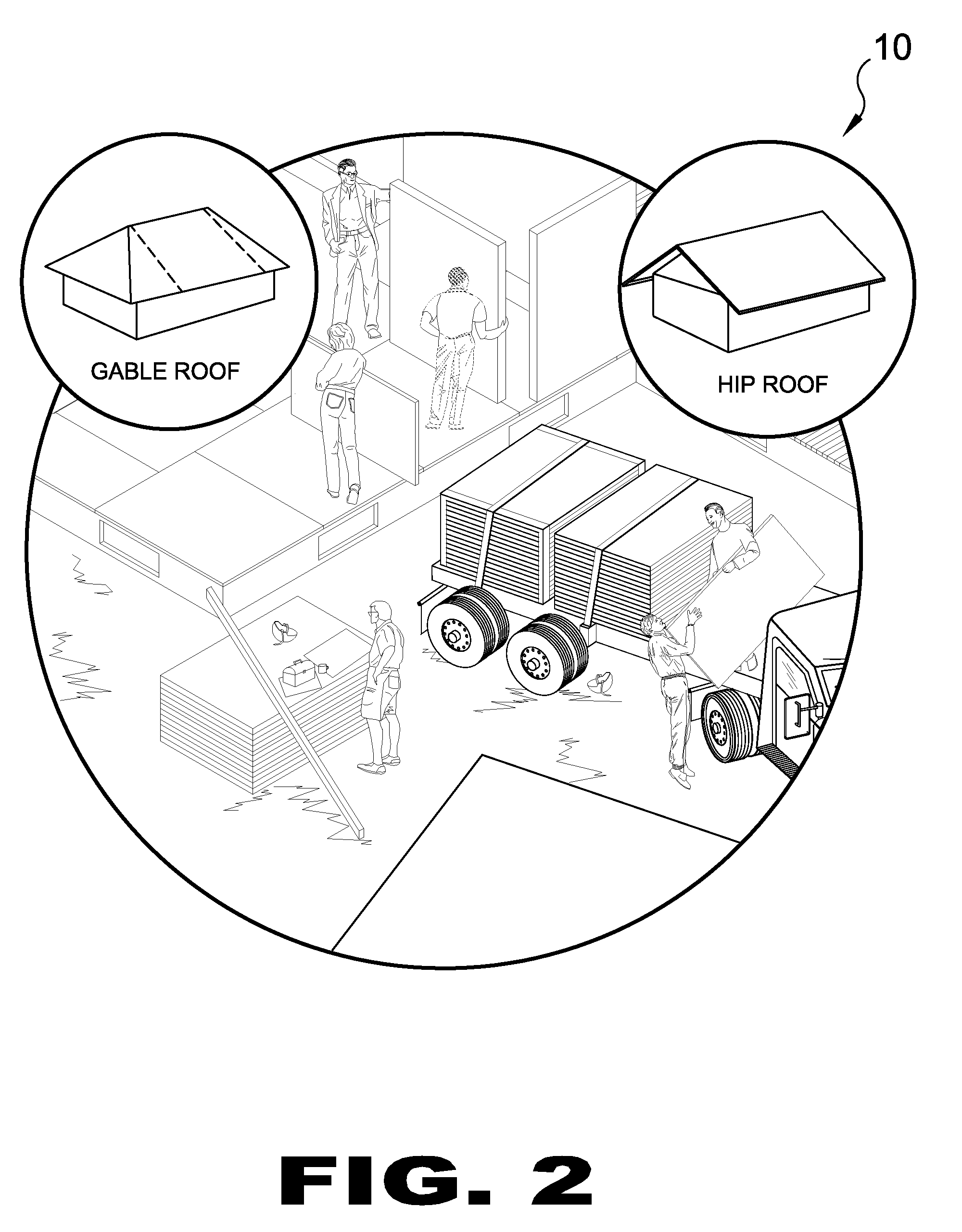
Prefabricated Building Components and Assembly Equipment
a technology of prefabricated building components and assembly equipment, applied in the field of building materials, can solve problems such as detrimental heat transfer, and achieve the effects of reducing the overall insulating value (r-value), eliminating any direct metal connection, and eliminating any thermal shorts
- Summary
- Abstract
- Description
- Claims
- Application Information
AI Technical Summary
Benefits of technology
Problems solved by technology
Method used
Image

Examples
Embodiment Construction
[0323]The following discussion describes in detail one embodiment of the invention (and several variations of that embodiment). This discussion should not be construed, however, as limiting the invention to those particular embodiments, practitioners skilled in the art will recognize numerous other embodiments as well. For definition of the complete scope of the invention, the reader is directed to appended claims.
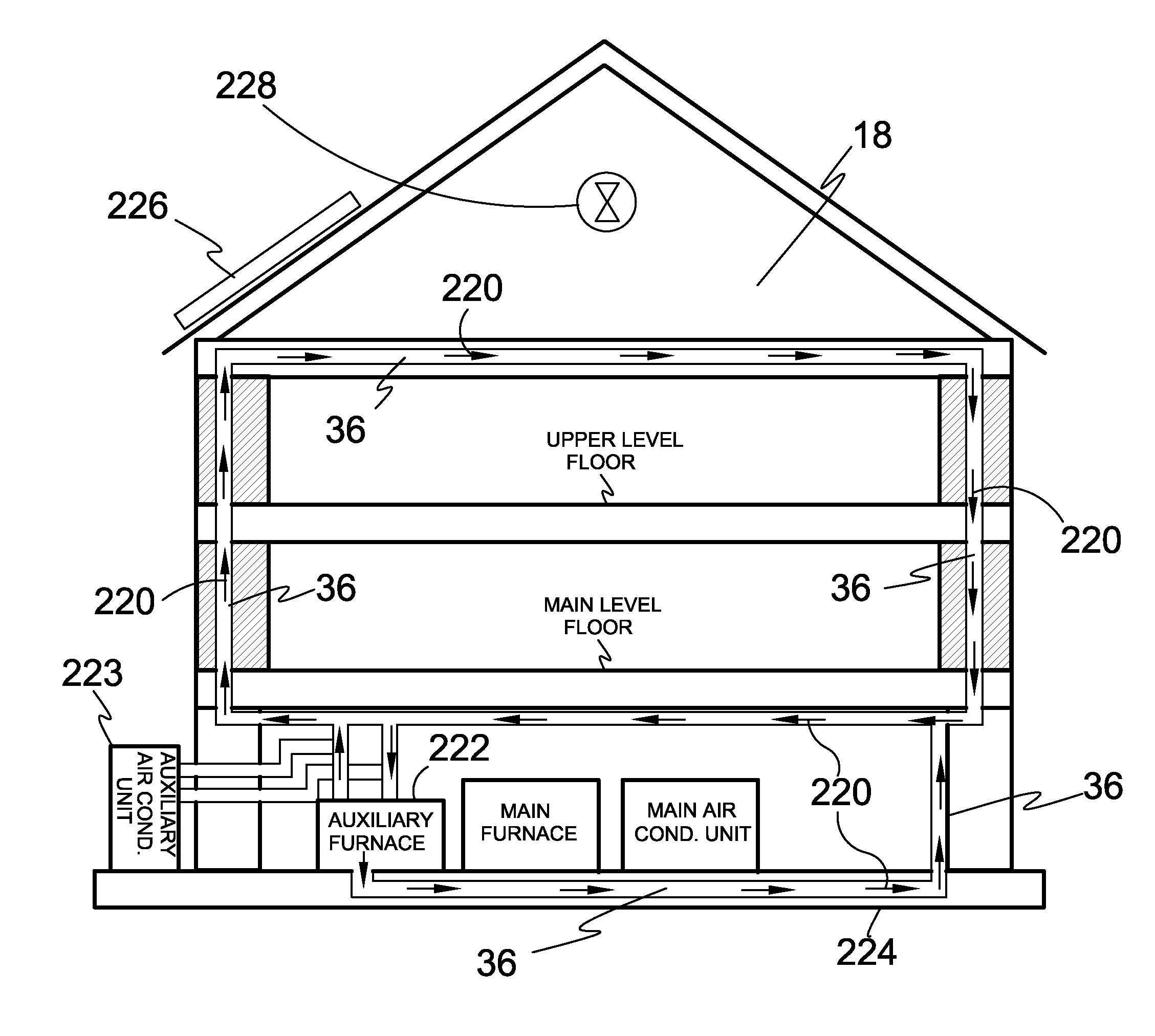
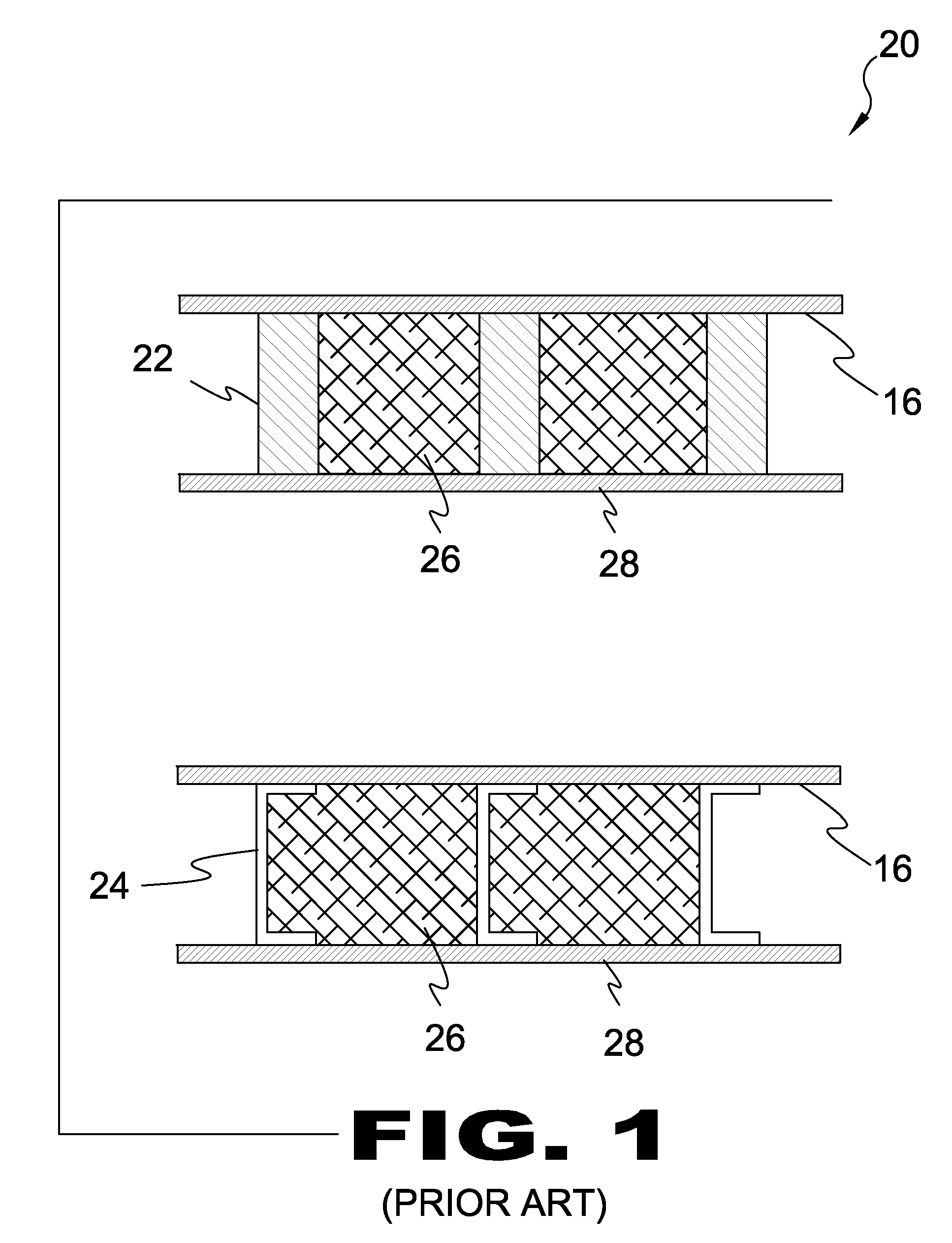
[0324]FIG. 1 is a top view of prior art. 20 Shown are two top views of prior art 20, first depicting the existing wood frame structure with 2×6 wood studs 22, the second depicting the existing steel frame structure with 2×6 “C” studs 24 with fiberglass insulation 26 disposed between the drywall 28 and the oriented strand board 16. The present invention is intended to improve the building process and offers better qualities in terms of value, structural integrity, comfort and energy conservation for industrial, commercial and residential building industries. The present inv...
PUM
 Abstract
Description
Claims
Application Information