
Burner having a protective element for ignition electrodes

a technology of ignition electrodes and protective elements, which is applied in the field of burners, can solve the problems of not being able to ignite gas mixture, not being able to replace ignition electrodes, and having negative effects on the operational reliability of ignition electrodes

Active Publication Date: 2011-05-26
SIEMENS ENERGY GLOBAL GMBH & CO KG
View PDF11 Cites 2 Cited by
  • Summary
  • Abstract
  • Description
  • Claims
  • Application Information

AI Technical Summary

Benefits of technology

[0012]The advantage of the solution lies in the fact that the ignition electrodes are protected and consequently damage during transportation or, as the case may be, during the installation and removal of the ignition electrodes can be avoided. Although a combustion chamber of a gas turbine having a burner is described in EP 0 193 838 B1, the ignition electrodes of the burner are not equipped with a protective element.
[0014]In one advantageous development the protective element is connected to the exterior of the burner such that the necessary stability is ensured.
[0018]The protective element is preferably manufactured from a flexurally resistant and shockproof material such that a deformation of the protective element that could lead to a deformation of the internal ignition electrodes is avoided.
[0019]A further advantageous development consists in the distance between the protective element and the ignition electrode being at least sufficiently great such that no sparkover occurs between the protective element and the ignition electrode when an ignition voltage is applied to the ignition electrode, thereby ensuring that a current sparkover between the ignition electrode and the protective element can be reliably avoided.

Problems solved by technology

If one or both of the ignition electrodes mounted on the pilot burner are damaged or bent during transportation or installation, this can have a negative effect on the operational reliability of the ignition electrodes.
Damage or bending can therefore make it become necessary to replace the ignition electrodes.
Replacing the ignition electrodes can also become necessary if one of the electrodes is bent to such an extent that a current sparkover occurs between an electrode lead and another metallic component instead of between the electrode tips and consequently the gas mixture cannot be ignited.
Furthermore, these igniters are not igniters for gas turbine burners.
However, the ignition electrodes that are used in the context of gas turbine burners and ignite with the aid of an ignition spark are adversely affected considerably more easily in their operational reliability by comparison with ignition electrodes of thermal igniters.

Method used


Image

  • Burner having a protective element  for ignition electrodes
  • Burner having a protective element  for ignition electrodes
  • Burner having a protective element  for ignition electrodes

Examples


Embodiment Construction

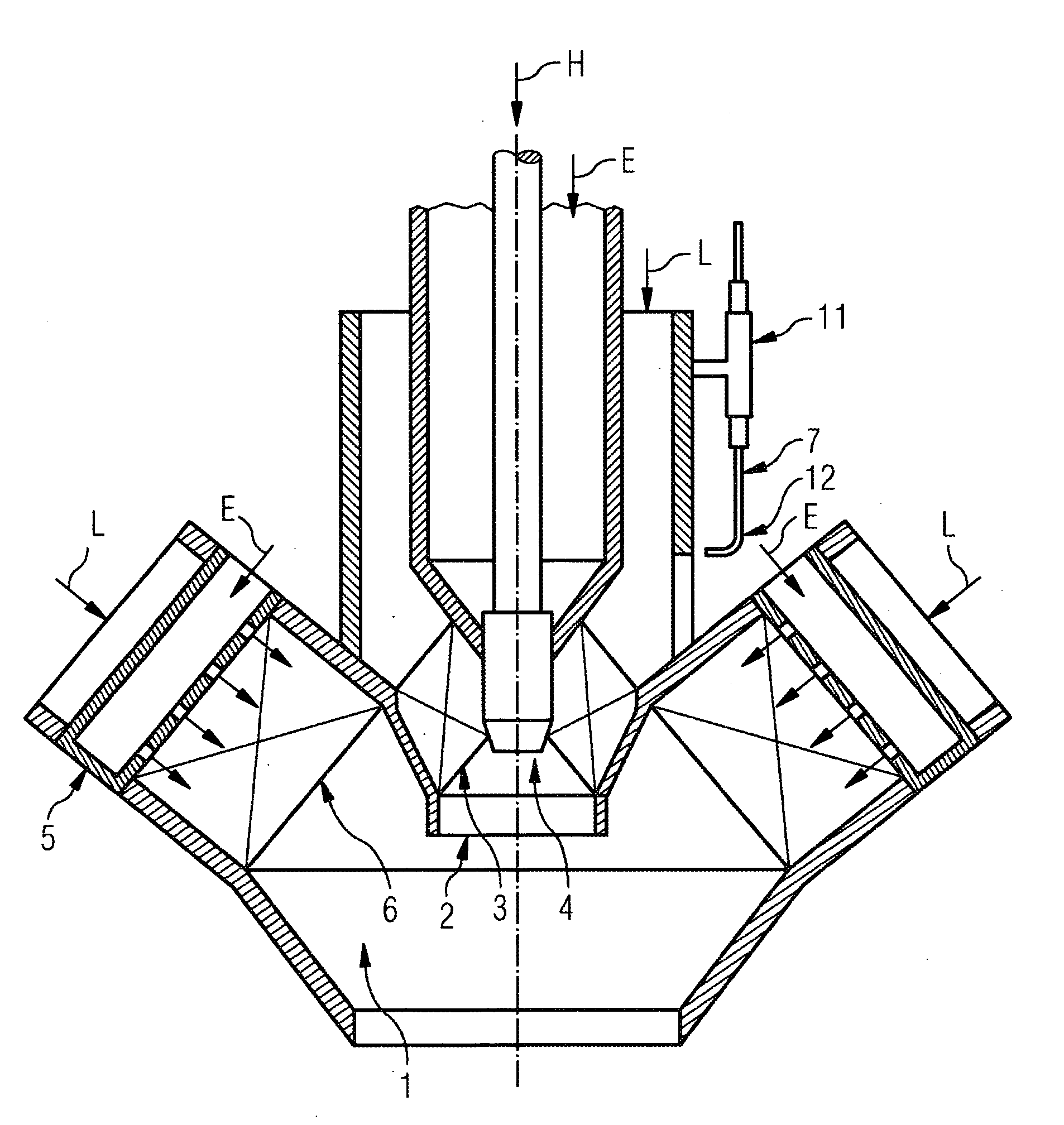
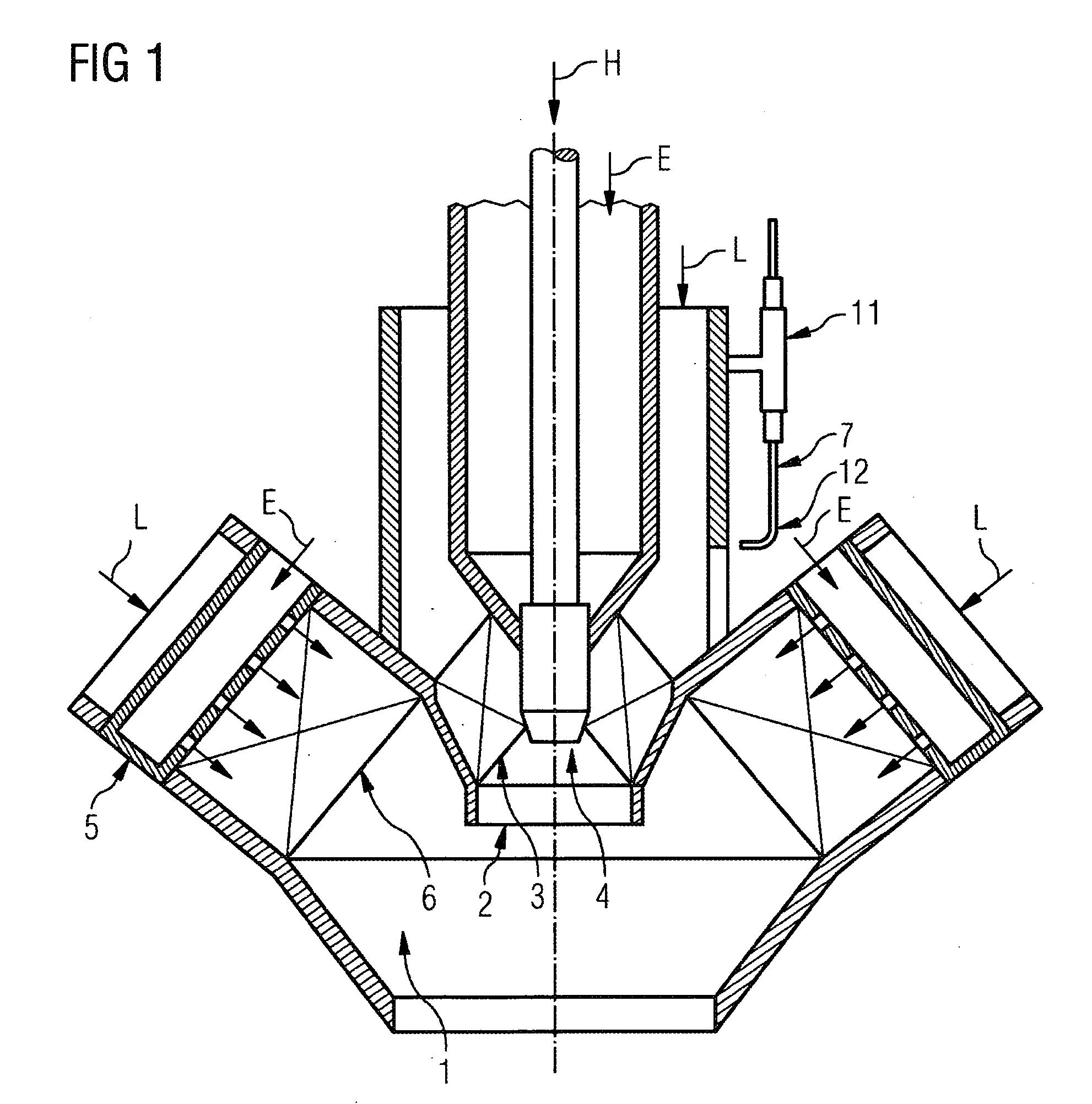
[0028]The burner arrangement shown in FIG. 1 belongs to a gas turbine system, the preferred field of application of the invention. However, the burner arrangement is also suitable for gas-fired combustion systems of boilers.

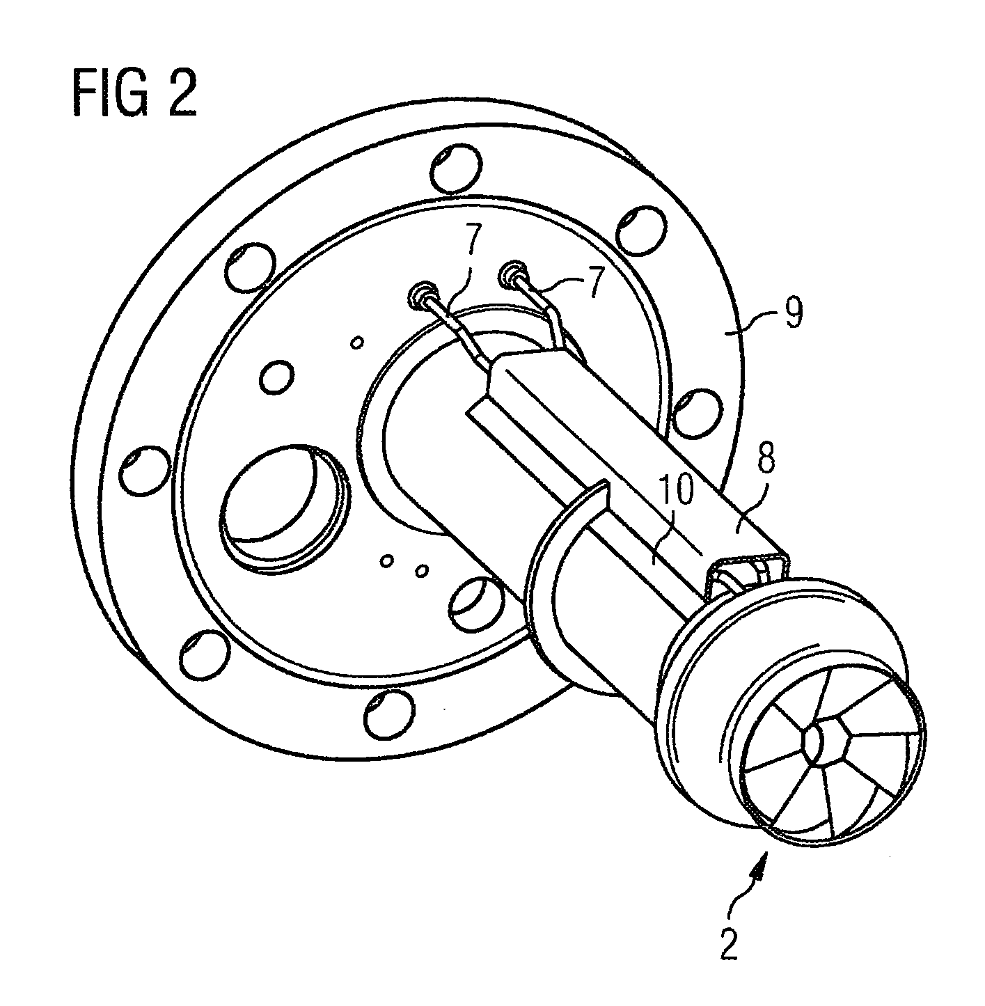
[0029]The burner arrangement consists of at least one first burner 2, which is mounted on a carrier plate (not shown in FIG. 1; see FIG. 2, 3) and serves as a pilot burner, and a second burner 1, which serves as a main burner and in the middle of which the first burner 2 is inserted coaxially. The first burner 2 has a burner head 4 with a swirl vane system 3 and can be operated with natural gas E and / or heating oil H as fuel. The head 4 of the first burner 2 is coaxially (referred to the burner axis) surrounded by an air inlet duct 6 which serves to supply the main part of the combustion air L to a combustion zone (not shown) embodied downstream of the burner head 4. The pressurized combustion air L is supplied to the annular gap by a compressor of the gas turbin...


PUM


Abstract

A gas turbine burner with an igniter and an ignition electrode for installation in a main burner of a gas turbine is disclosed. The ignition electrode is protected from damage by a protective element.

Description

CROSS REFERENCE TO RELATED APPLICATIONS[0001]This application is the US National Stage of International Application No. PCT / EP2007 / 058411 filed Aug. 14, 2007 and claims the benefit thereof. The International Application claims the benefits of European Patent application No. 06017534.6 EP filed Aug. 23, 2006, both of the applications are incorporated by reference herein in their entirety.FIELD OF INVENTION[0002]The invention relates to a burner having an igniter and at least one ignition electrode, in particular an ignition electrode of a type suitable for installation in a burner of a gas turbine.BACKGROUND OF INVENTION[0003]A burner embodied as a pilot burner having an igniter and ignition electrodes leading to the igniter is described in EP 0 193 838 B1, for example. The igniter has the task of igniting the fuel. The ignition electrodes are fixed on the exterior of the pilot burner and run parallel to its longitudinal axis. The fuel supply is located in the interior of the pilot b...

Claims


Application Information

Patent Timeline
IPC IPC(8): F02C7/266F23Q3/00
CPCF23Q3/006F23Q9/00F23Q7/24
Inventor BÖTTCHER, ANDREASKLUGE, ANDREKRUSCH, CLAUSPFEIFFER, ELMARTÜSCHEN, SABINE
Owner SIEMENS ENERGY GLOBAL GMBH & CO KG
Learn More