

Exhaust gas treatment device
a technology of exhaust gas treatment and exhaust gas, which is applied in the direction of machines/engines, mechanical equipment, separation processes, etc., can solve the problems of degrading the operation efficiency of cleaning operations, degrading the efficiency of inspection operations, and emitted harmful substances of diesel engines
- Summary
- Abstract
- Description
- Claims
- Application Information
AI Technical Summary
Benefits of technology
Problems solved by technology
Method used
Image

Examples
Embodiment Construction
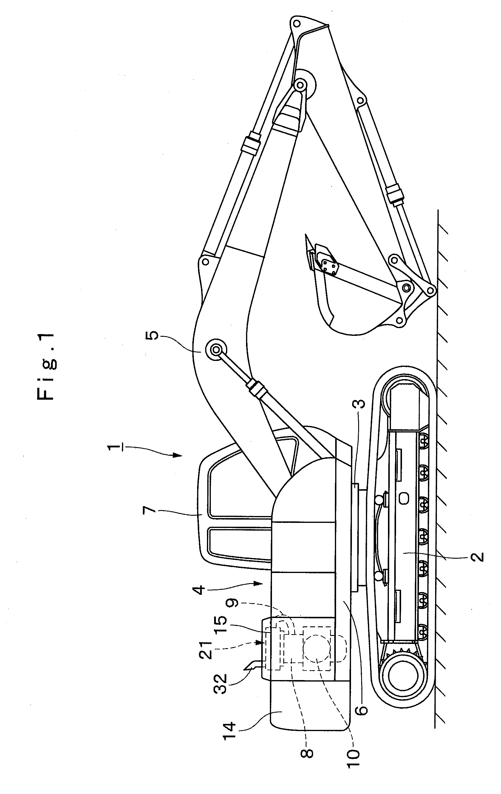
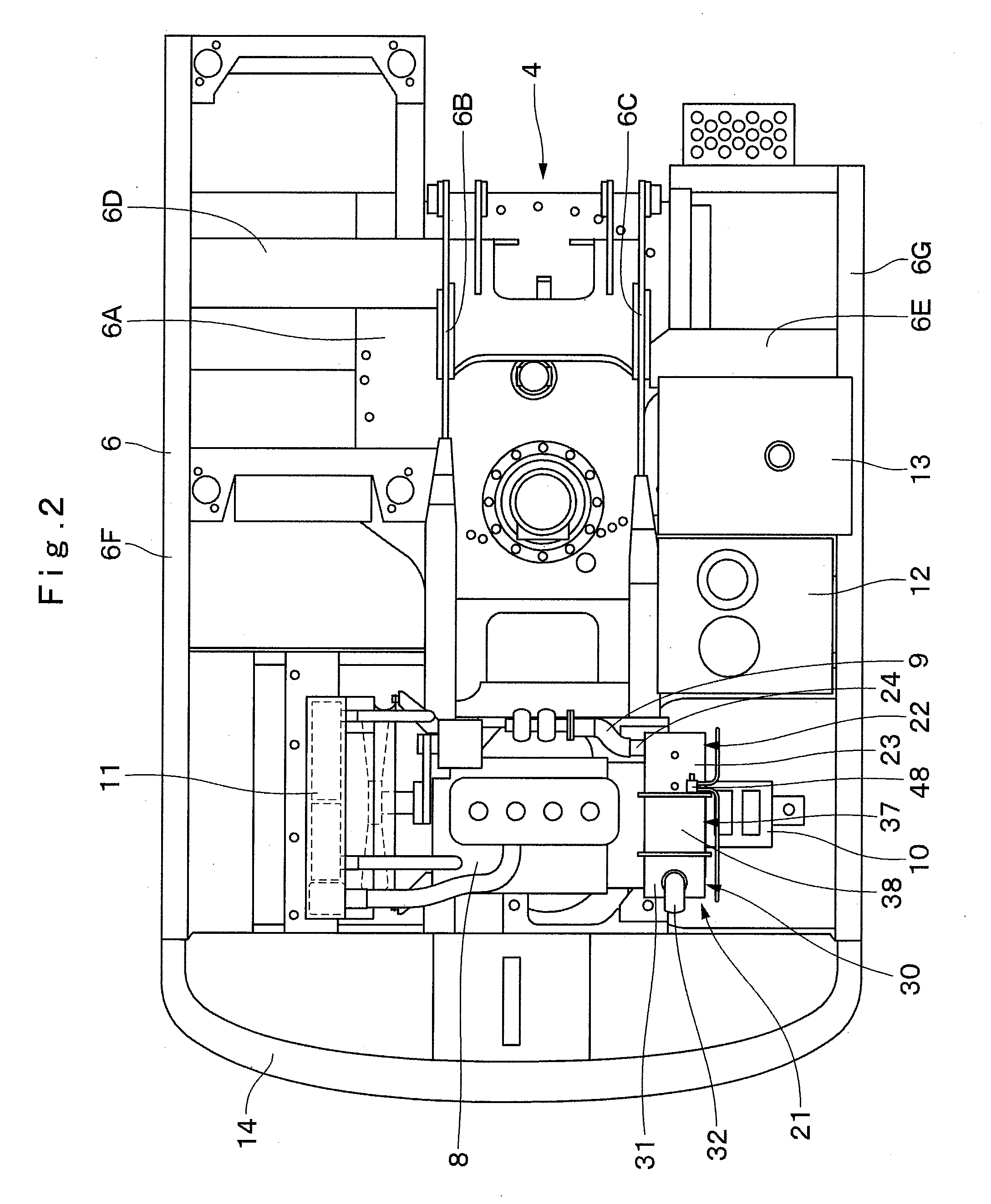
[0073]Hereinafter, the embodiments of an exhaust gas treatment device in accordance with the present invention is described more particularly with reference to the accompanying drawings, by citing as an example a case where the exhaust gas treatment device is applied to a hydraulic excavator.
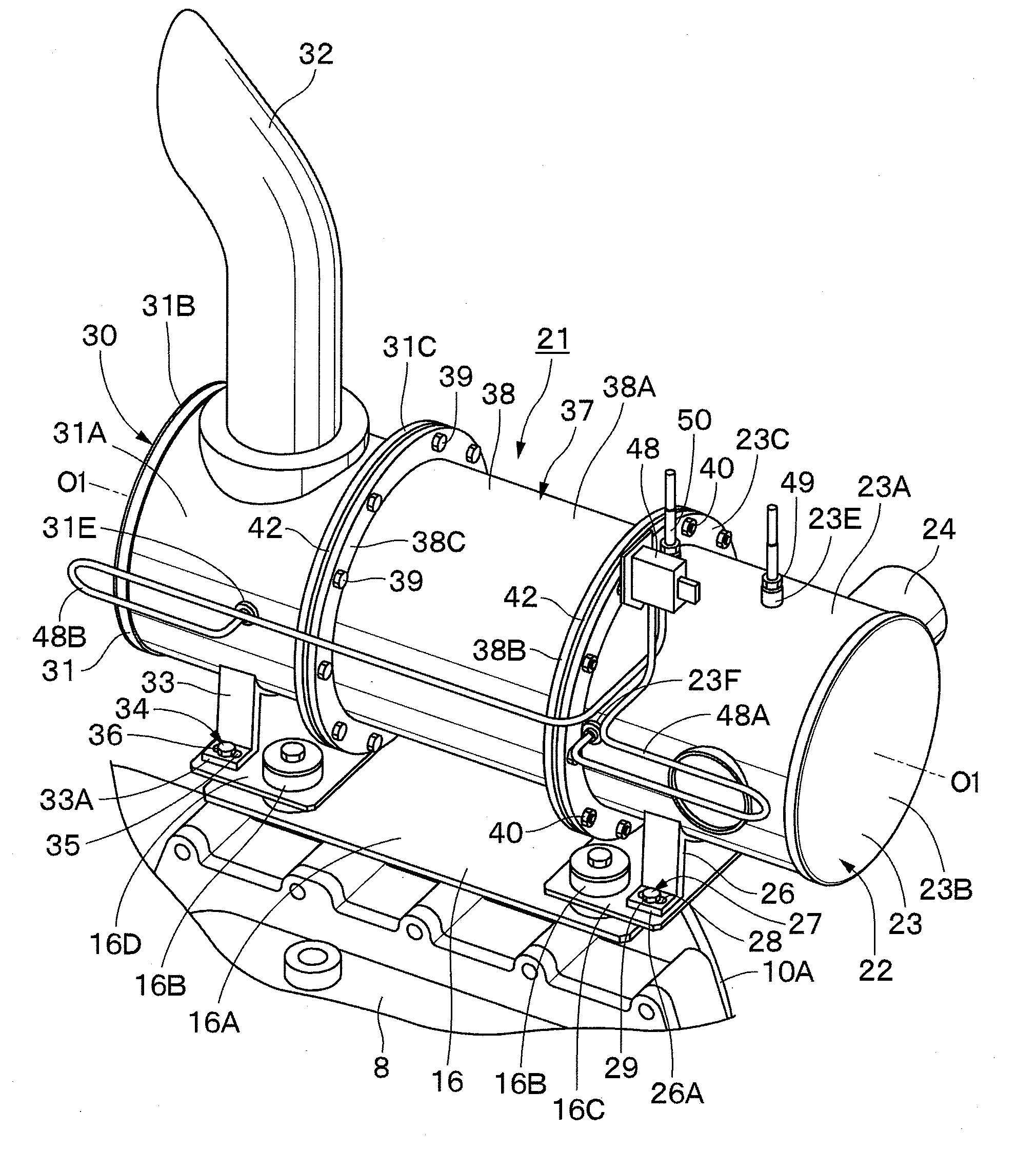
[0074]FIGS. 1 to 15 show a first embodiment of the present invention. In this embodiment, a particulate matter removing device (PM removing device) for removing by a particulate matter removing filter (DPF) particulate matter (PM) emitted from an engine is illustrated as an example of the exhaust gas treatment device.
[0075]The exhaust gas treatment device used in the first embodiment is constructed such that three cylinders, namely, an upstream cylinder with oxidation catalyst and a muffler cylinder accommodated therein, a downstream cylinder with a muffler cylinder accommodated therein, and a filter accommodating cylinder with the DPF accommodated therein, are connected together in series in th...
PUM
 Abstract
Description
Claims
Application Information