Supercharge Your Innovation With Domain-Expert AI Agents!

Crankcase vent nozzle for internal combustion engine

a technology for internal combustion engines and vent nozzles, which is applied in the direction of combustion engines, combustion air/fuel air treatment, charge feed systems, etc., can solve the problems of pcv/ccv system significant additional cost, ice formation at the outlet of pcv/ccv, and the leakage of combustion gas between the cylinder and its piston rings into the engine crankcase, etc., to achieve the effect of reducing or preventing ice formation

Active Publication Date: 2011-05-26
GM GLOBAL TECH OPERATIONS LLC
View PDF4 Cites 4 Cited by
  • Summary
  • Abstract
  • Description
  • Claims
  • Application Information

AI Technical Summary

Benefits of technology

The patent describes a nozzle that prevents ice formation in an engine's air intake. This nozzle has an aerodynamic shape that prevents ice from accumulating on the walls of the air inlet adapter. The patent also describes a crankcase ventilation system that includes a nozzle to prevent ice formation. The nozzle has a leading edge and a trailing edge that extend into the air inlet adapter. The system includes an engine block assembly and an axially extending air inlet adapter, with the nozzle being fluidly coupled between them. The nozzle has an airfoil portion with a leading edge and a trailing edge that extend into the air inlet adapter at different lengths. The technical effects of this invention include reducing ice formation in the engine's air intake and improving crankcase ventilation.

Problems solved by technology

During engine operation, combustion gas may leak between the cylinder and its piston rings into the engine crankcase.
Each of these solutions add a significant additional cost to a PCV / CCV system.
Even with some heating systems, freezing can still occur at the outlet of the PCV / CCV system where blowby gas is introduced into the intake side of the engine.
Ice build-up at this location can damage engine components downstream, such as a turbocharger compressor / impeller wheel or throttle control valve.
Even if damage is avoided, ice-build-up can cause restrictions in the engine intake which may affect engine performance or fuel economy.

Method used


Image

  • Crankcase vent nozzle for internal combustion engine
  • Crankcase vent nozzle for internal combustion engine
  • Crankcase vent nozzle for internal combustion engine

Examples


Embodiment Construction

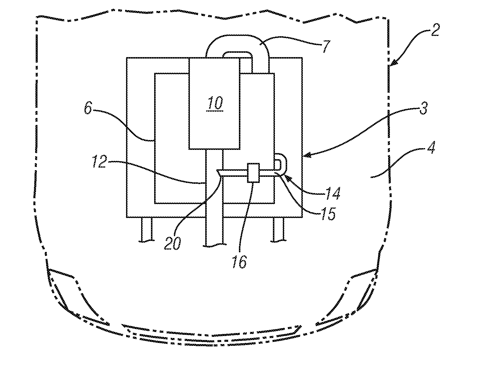
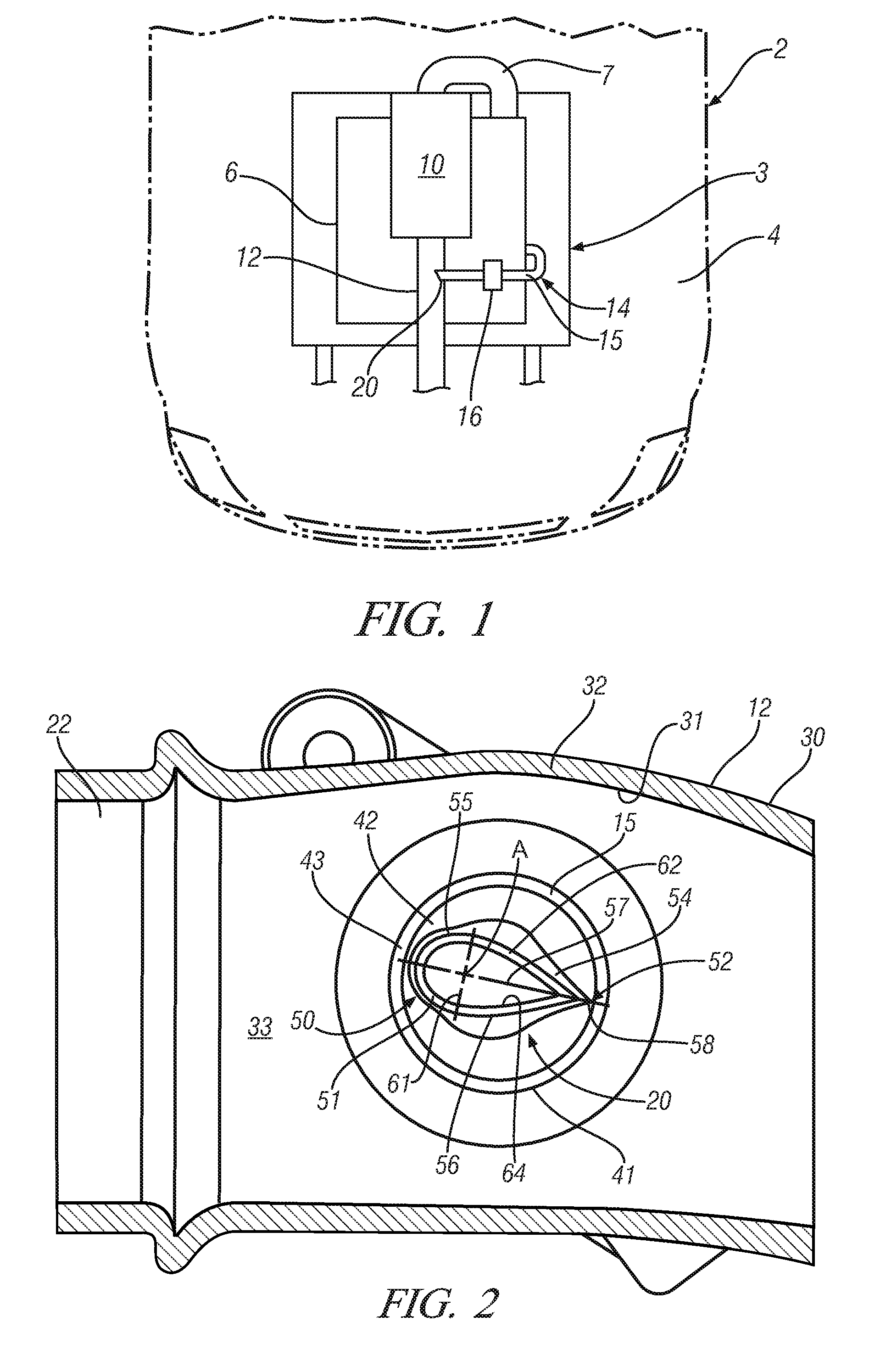
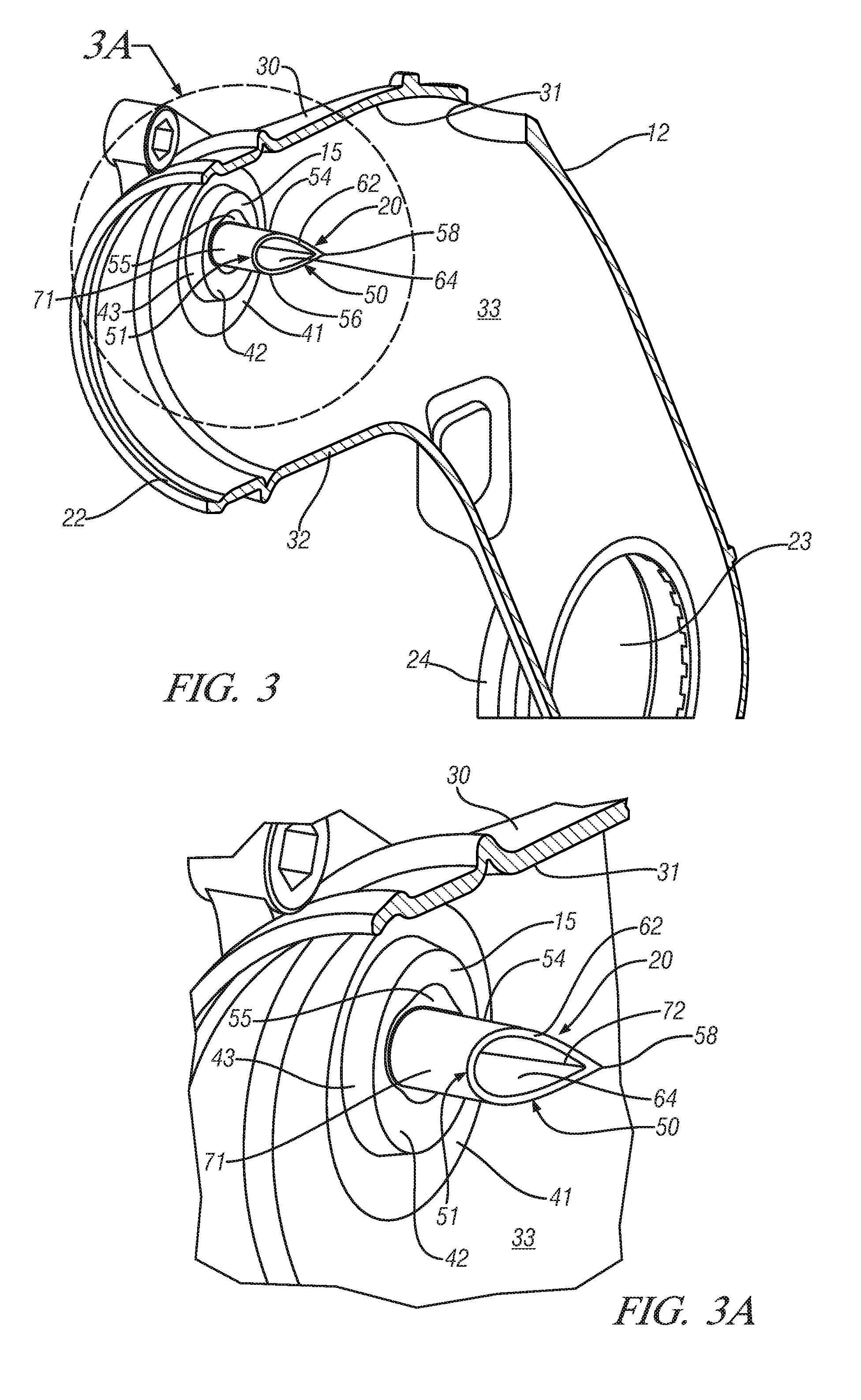
[0018]Referring now to the Figures, where the invention will be described with reference to specific embodiments, without limiting same, a functional diagram of a vehicle 2 having an internal combustion engine block assembly 3 located within an engine compartment 4 is shown in FIG. 1. An air intake manifold 6, having a gas intake plenum 7 is fluidly coupled to a turbocharger 10. Air intake manifold 6 generally includes a plurality of gas outlets (not shown) that are fluidly connected to engine block assembly 3. Specifically, an air intake system or air inlet adapter 12 feeds air gases into a turbocharger 10 where the gases are pressurized and flow from air intake manifold 6 to the engine block assembly 3. A crankcase ventilation (PCV / CCV) system 14 is used to ventilate the crankcase and recirculate blowby gas from an inlet tube 15 through a PCV / CCV valve 16 and out through a nozzle 20 to the turbocharger inlet adapter 12. As is known, the introduction of blowby gas to the inlet adap...


PUM


Abstract

A crankcase ventilation system is provided. The crankcase ventilation system is fluidly coupled between an engine block assembly and an axially extending air inlet adapter. A crankcase vent nozzle is provided as one aspect of the system and extends into the air inlet adapter. The crankcase vent nozzle has a leading edge portion and a trailing edge portion extending radially into an axially extending flow path in the air inlet adapter. The trailing edge portion extending further into the flow path than the leading edge portion.

Description

FIELD OF THE INVENTION[0001]Exemplary embodiments of the present invention are related to an engine ventilation system regardless of technical definition such as a closed crankcase ventilation (CCV) system generally used for Diesel engine applications or positive crankcase ventilation (PCV) system and, more specifically, to a vent nozzle for the system.BACKGROUND[0002]During engine operation, combustion gas may leak between the cylinder and its piston rings into the engine crankcase. The leaked combustion gas is referred to as piston blowby gas and may comprise unburned intake air / fuel mixture, exhaust gas, oil mist, and water vapor.[0003]A crankcase ventilation system be it PCV or CCV, is typically employed to ventilate the crankcase and recirculate the blowby gas to the intake side of the engine for burning the gas in the combustion chamber. The PCV / CCV system takes advantage of the negative pressure in the intake to draw the gas out of the crankcase and may utilize a PCV / CCV valv...

Claims


Application Information

Patent Timeline
Patent Type & Authority Applications(United States)
IPC IPC(8): F01M13/00
CPCF01M2013/027F01M13/022
Inventor VELOSA, JULIANHUEBLER, MARK S.HUNSANGER, CARL RAYMONDPUNG, JONATHANFARRAR, STEPHEN W.JOHNSON, LAUN M.
Owner GM GLOBAL TECH OPERATIONS LLC
Features
  • R&D
  • Intellectual Property
  • Life Sciences
  • Materials
  • Tech Scout
  • Unparalleled Data Quality
  • Higher Quality Content
  • 60% Fewer Hallucinations
Learn More