
Solar module, solar module support, and photovoltaic power generation system

a solar module and solar panel technology, applied in the direction of heat collector mounting/support, pv power plants, light and heating equipment, etc., can solve the problems of affecting the like, so as to improve the strength of solar panels including the reinforcing frame members, increase the manufacture time or installation time, and facilitate the effect of manufacturing and installation

Inactive Publication Date: 2011-05-26
SHARP KK
View PDF11 Cites 4 Cited by
  • Summary
  • Abstract
  • Description
  • Claims
  • Application Information

AI Technical Summary

Benefits of technology

[0053]According to the present invention, the reinforcing-frame supporting member is provided so that the main axis of the reinforcing-frame supporting member and the main axis of the reinforcing frame member intersect at different heights. Therefore, the reinforcing-frame supporting member can be provided to span between the sub-frame members while intersecting the reinforcing frame member, without changing or modifying the reinforcing frame member and with the strength being maintained.
[0054]Therefore, in the aforementioned solar module including the reinforcing-frame supporting member, the reinforcing-frame supporting member can be attached to the solar module without significantly changing or modifying the structure of the solar module.
[0055]Therefore, the strength of the solar module including the reinforcing frame member can be improved without significantly changing or modifying the structure of the solar module. The solar module can be easily manufactured and installed at an installation site, and an increase in the manufacture time or installation time, an increase in cost, and the like can be prevented.

Problems solved by technology

Recently, a sudden gust of wind or the like is likely to occur due to a natural hazard, such as a typhoon or the like.

Method used


Image

  • Solar module, solar module support, and photovoltaic power generation system
  • Solar module, solar module support, and photovoltaic power generation system
  • Solar module, solar module support, and photovoltaic power generation system

Examples


Embodiment Construction

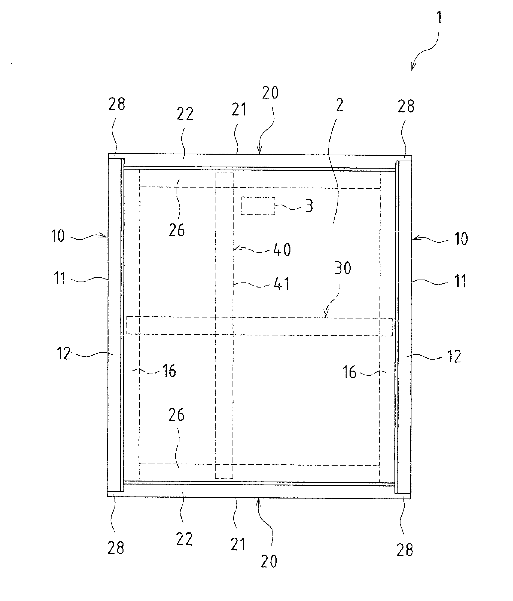
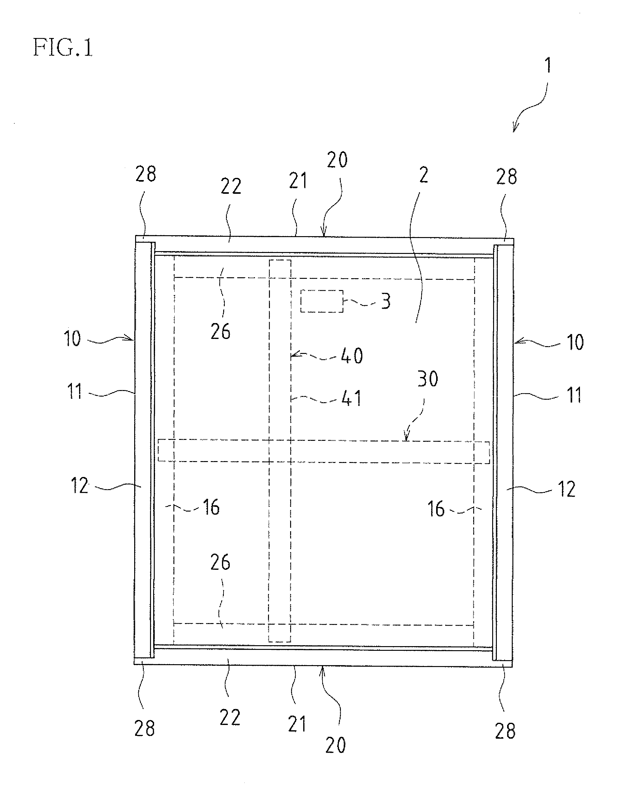
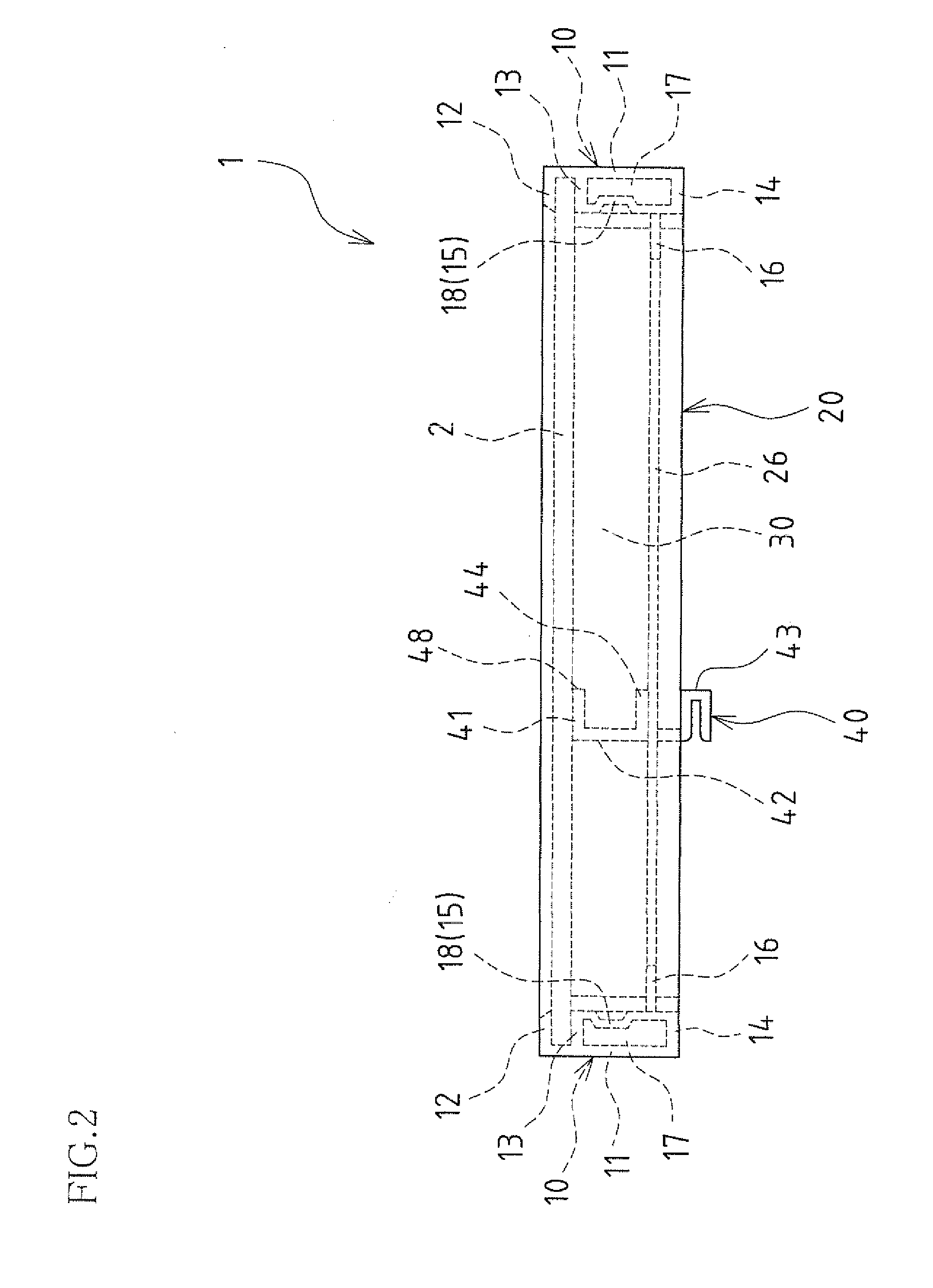
[0072]Next, a solar module according to an embodiment of the present invention will be described with reference to the accompanying drawings. FIGS. 1, 2, 3, and 4 are plan, front, side, and bottom views of the solar module 1 of this embodiment, respectively. FIG. 5 is a partial perspective view of frame members of the solar module 1 as viewed from the inside. Note that a solar cell panel 2 is not shown in FIG. 5.

[0073]As shown in FIGS. 1-5, the solar module 1 of this embodiment mainly includes a rectangular solar cell panel 2 and frame members. The frame members include a pair of main frame members 10 and 10, and a pair of sub-frame members 20 and 20. The solar cell panel 2 has outer dimensions of about 1150 mm×about 1000 mm. As shown in FIGS. 1 and 4, an output terminal box 3 via which an output of the solar cell panel 2 is extracted is provided on the back surface of the solar cell panel 2.

[0074]The solar cell panel 2 is held by the pair of main frame members 10 and 10 holding mai...


PUM


Abstract

A solar module according to an embodiment of the present invention includes a solar cell panel 2, main frame members 10 each including a main holder configured to hold the solar cell panel 2, sub-frame members 20 each including a sub-holder configured to hold the solar cell panel 2, a reinforcing frame member 30 provided to span between the main frame members 10, and a reinforcing-frame supporting member 40 provided to span between the sub-frame members 20 while intersecting the reinforcing frame member 30, and including a concave portion configured to straddle a bottom surface of the reinforcing frame member 30 from below at a portion where the reinforcing-frame supporting member 40 intersects the reinforcing frame member 30.

Description

TECHNICAL FIELD[0001]The present invention relates to solar modules that hold a solar cell panel using a frame member coupled with a reinforcing frame member, solar module supports, and photovoltaic power generation systems.BACKGROUND ART[0002]Solar modules typically include a rectangular solar cell panel and a frame member for holding the solar cell panel. For the frame member used in the solar module, a variety of structures have been proposed.[0003]Among the known frame structures is one that includes an outer wall that is vertically formed along an edge of the solar cell panel and a holder that is horizontally formed at an upper portion of the outer wall and has a U-shaped cross-section (see, for example, FIGS. 2 and 5 in Patent Document 1). The edge of the solar cell panel is put into the holder with the U-shaped cross-section so that the solar cell panel is clamped by the holder, whereby a solar module is constructed.[0004]In recent years, as the size of the solar module havin...

Claims


Application Information

Patent Timeline
IPC IPC(8): H01L31/048
CPCF24J2/5211F24J2/5254H02S30/10Y02E10/47Y02E10/50F24J2002/4656F24S2080/09F24S25/632F24S25/20
Inventor TERUNUMA, MIHOOHKOSHI, YASUSHI
Owner SHARP KK
Learn More