
Fluid transfer device having leak indication and method of making same

Active Publication Date: 2011-05-26
GREAT LAKES COPPER
View PDF24 Cites 27 Cited by
  • Summary
  • Abstract
  • Description
  • Claims
  • Application Information

AI Technical Summary

Benefits of technology

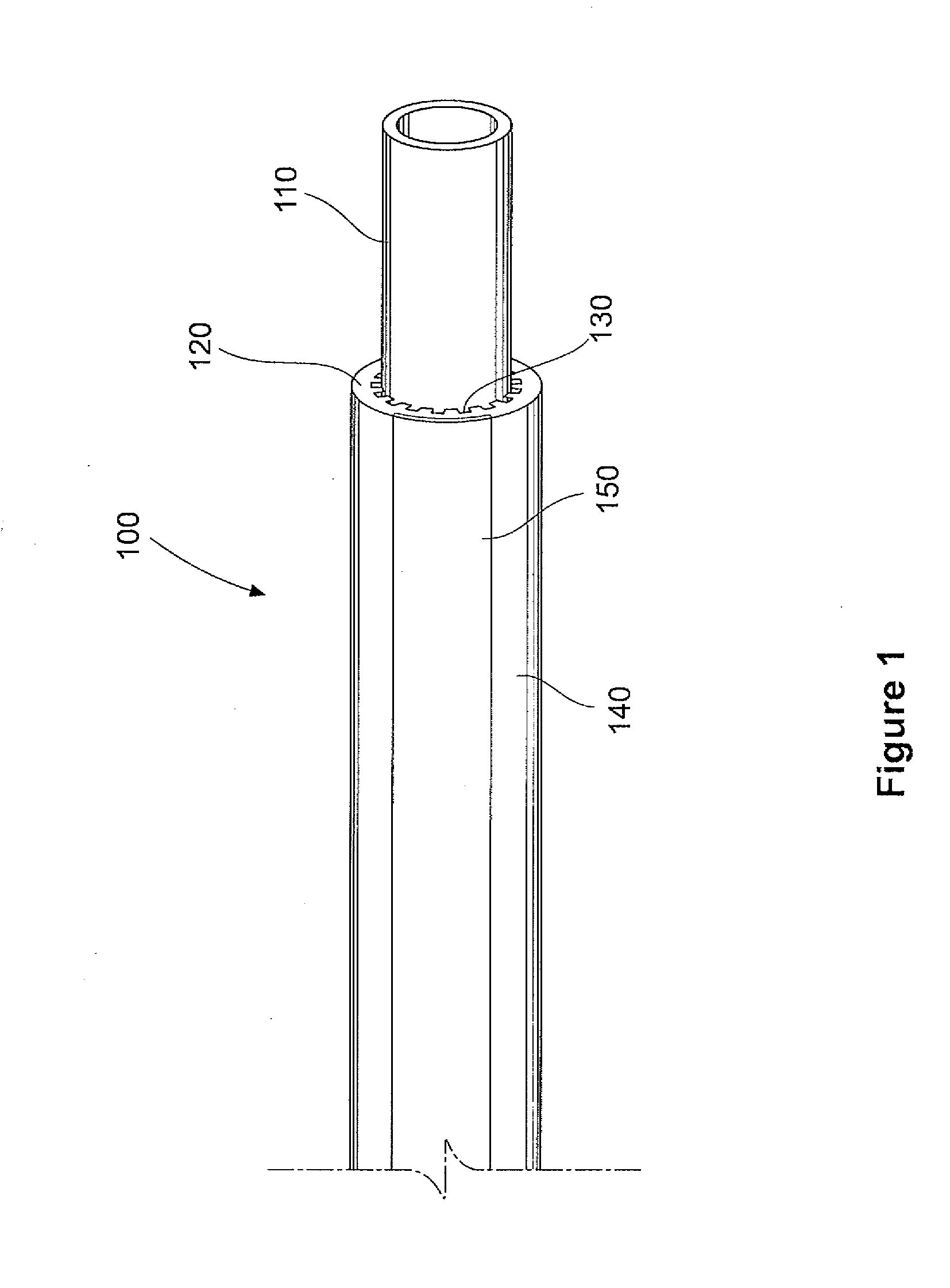
[0007]An object of the present invention is to provide a fluid transfer device having visual indication, and a method of making same. In accordance with an aspect of the present invention, there is provided a fluid transfer device comprising a conduit configured to transfer a fluid, said conduit havin

Problems solved by technology

Because of oil contamination, difficulty of clean up and / or use in areas where pipes and tubes are not always accessible along their entire length, there are concerns relating to undetected failures.
Similar conditions and issues are also experienced in other types of piping and tubing applications, including water pipes, natural gas lines, high and low pressure gas lines, or other fluid transfer conduits that would be known to a person skilled in the art.
Coated copper tubes, using both grooved and smooth inner surfaces, have been manufactured but may not meet certain code conditions relating to tubing type and use identification.
Should the inner copper tube get fractured, or through corrosion develop a leak, the contents (for example, red heating oil) will leak out into the space between the sleeve and the tube.
In some locations, not all parts of a tube or pipe are capable of being visually inspected because, for example, they are behind walls or other objects, underground, or otherwise difficult to access.

Method used


Image

  • Fluid transfer device having leak indication and method of making same
  • Fluid transfer device having leak indication and method of making same
  • Fluid transfer device having leak indication and method of making same

Examples


example 1

Method of Manufacture

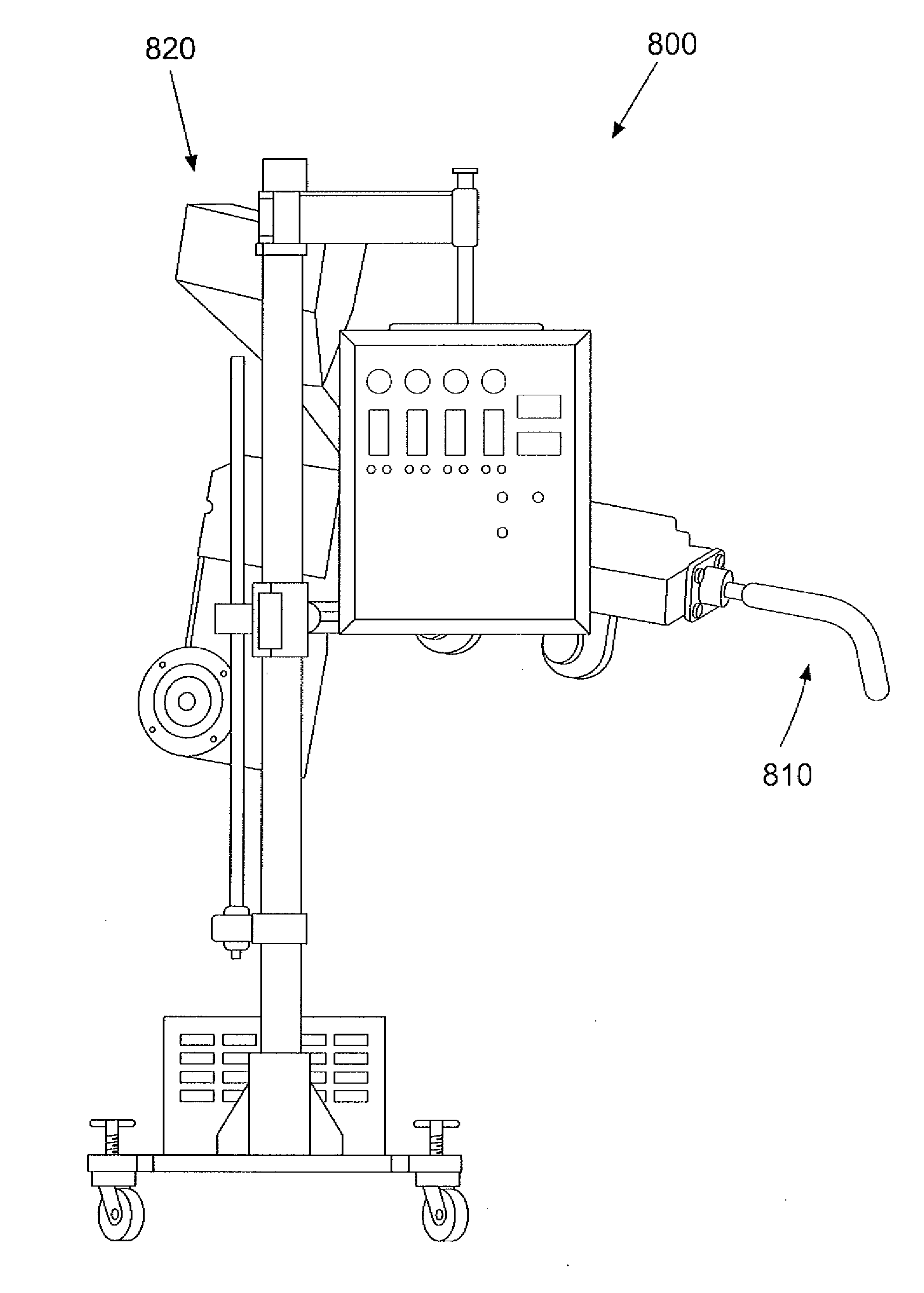
[0084]With reference to FIGS. 4, 8 and 9, there is provided an extrusion process wherein a plastic feed material (such as granulated polyethylene or polyvinyl chloride resin) is fed into a first heated inlet extruder cavity, feeder or cylinder 820, 910, such as those shown in FIG. 8 or 9. Typically, the raw plastic is in a bead form and is often mixed with additives and / or colourants before the extrusion process begins. In this embodiment, there is no colourant additive for the primary sheath material and initial extrusion. Colourant additive is introduced by the second co-extrusion device 420 as striping applied to the sheath in a controlled portion of the extruding device 440 prior to exiting the dies. Once inside the plastic extrusion machine 900, the plastic beads or pellets move through an opening in the first extruder cavity 910 towards a screw mechanism 940 in a second extruder cavity 920. The screw rotates, forcing the plastic material to advance through...

example 2

Apparatus for Making Fluid Transfer Device

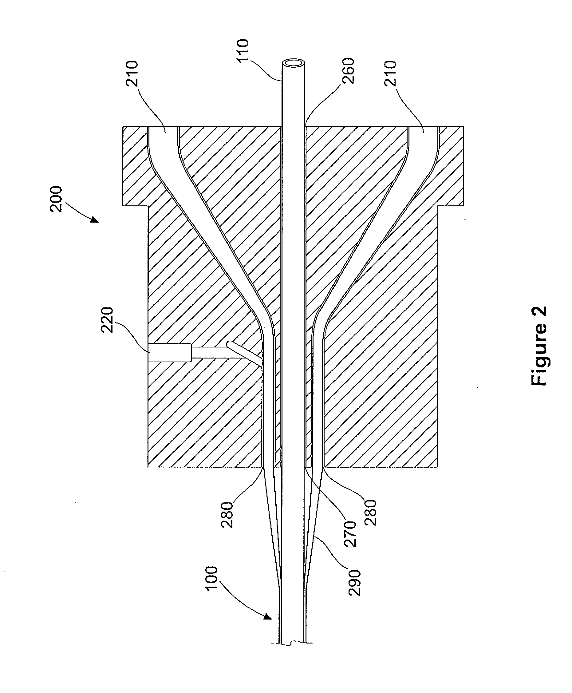
[0096]With reference to FIGS. 6 and 7, there is disclosed an apparatus for making a fluid transfer device. FIG. 6 shows a cross-sectional side view of the apparatus 600 and FIG. 7 shows a cross-sectional front view of the apparatus 600. The apparatus 600 according to this exemplary embodiment comprises a die 605 for receiving a conduit via the conduit receiving location 640 and one or more extruding materials via inlets 610, 660. The conduit passes through the apparatus at the conduit outlet 650 located substantially near extrusion outlets 620. The extrusion bores 615 extend from the extrusion inlets 610 to the extrusion outlets 620 and the co-extrusion inlets 660 provide for application of second extrusion materials to a fluid transfer device. Slot 690 provides a means for applying a strip of second extrusion material to the sheath. In some embodiments, a saw cut 680 provides for a means of machining slot 690 into the die. FIG. 7 depicts a ...


PUM

PropertyMeasurementUnit
Lengthaaaaaaaaaa
Transparencyaaaaaaaaaa
Perimeteraaaaaaaaaa

Abstract

A fluid transfer device and methods and apparatuses for making same is provided. The fluid transfer device comprises a conduit configured to transfer a fluid. The fluid transfer device further comprises a sheath surrounding the perimeter of the conduit and extending along at least part of the length of the conduit. In some embodiments, the interior of the sheath may be grooved to facilitate movement of the fluid from the location or locations of a leak or leaks along the length of the fluid transfer device. The sheath comprises one or more leak detection portions configured to provide an indication of fluid leaking from the conduit.

Description

CROSS-REFERENCE TO RELATED APPLICATION[0001]The present application claims priority to U.S. Provisional Patent Application No. 61 / 244,670 filed Sep. 22, 2009, the contents which are hereby incorporated by reference in their entireties.FIELD OF THE INVENTION[0002]The present invention pertains to field of fluid transfer devices, and fluid detection devices with leak detection. The present invention also pertains to field of use and manufacturing of fluid detection devices.BACKGROUND[0003]Within the heating oil industry, for example, due to the flexibility and ease of installation, copper tube has become the product of choice for conveying heating oil to homes or commercial installations. Because of the adverse conditions the tubing may be exposed to in some applications, on-site sleeving or factory coated copper has now become the industry norm in most areas. The tubing is often found in basements where it may be exposed to concrete or in corrosive soil conditions. Because of oil con...

Claims


Application Information

Patent Timeline
IPC IPC(8): F15D1/00D01D5/24B29C48/09B29C48/12B29C48/151B29C48/19B29C48/20
CPCB29C47/0023B29C47/003B29C47/021B29C47/064G01M3/04F16L39/005F16L2201/30F16L9/18F16L9/19B29C48/09B29C48/12B29C48/151B29C48/19B29C48/20Y10T137/8158
Inventor SIGOUIN, BRADLEY JOSEPH AUREL
Owner GREAT LAKES COPPER
Learn More