Adhesive tape joining apparatus and adhesive tape joining method

a technology of adhesive tape and adhesive tape, which is applied in the direction of chemistry apparatus and processes, solid-state devices, layered products, etc., can solve the problems of reducing pressure, avoiding conventional methods, and large apparatus in size, and achieves the effect of improving processing speed

Inactive Publication Date: 2011-05-26
NITTO DENKO CORP
View PDF5 Cites 4 Cited by
  • Summary
  • Abstract
  • Description
  • Claims
  • Application Information

AI Technical Summary

Benefits of technology

[0007]This invention has one object to provide apparatus and method of joining an adhesive tape that allows miniaturization of the apparatus for an enhanced processing speed as well as accurate joining of the adhesive tape over the semiconductor wafer and the ring frame.

Problems solved by technology

The foregoing conventional method, however, has the following problem.
That is, in the conventional apparatus, all mechanisms including the wafer, the ring frame, and the joining roller have to be housed in the chamber, which leads to larger apparatus in size.
Accordingly, inconvenience may occur that it takes more time to reduce pressure as the chamber has a larger volume, thereby taking a longer total processing time.

Method used


Image

  • Adhesive tape joining apparatus and adhesive tape joining method
  • Adhesive tape joining apparatus and adhesive tape joining method
  • Adhesive tape joining apparatus and adhesive tape joining method

Examples


Embodiment Construction

[0036]The invention is described more fully hereinafter with reference to the accompanying drawings, in which embodiments of the invention are shown. This invention may, however, be embodied in many different forms and should not be construed as limited to the embodiments set forth herein. Rather, these embodiments are provided so that this disclosure is thorough, and will fully convey the scope of the invention to those skilled in the art. In the drawings, the size and relative sizes of layers and regions may be exaggerated for clarity. Like reference numerals in the drawings denote like elements.

[0037]One exemplary embodiment of this invention will be described in detail hereinafter with reference to the drawings.

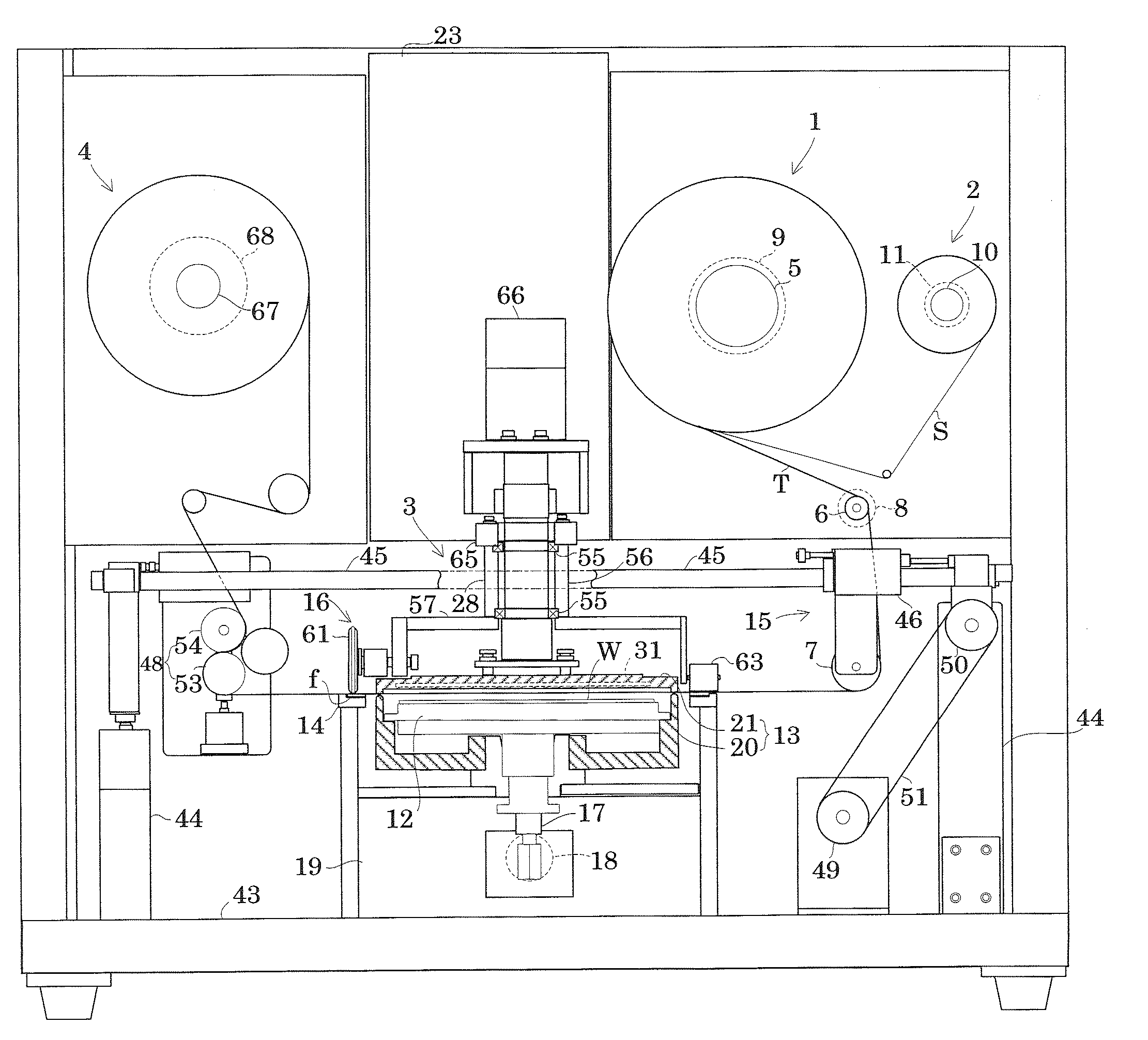
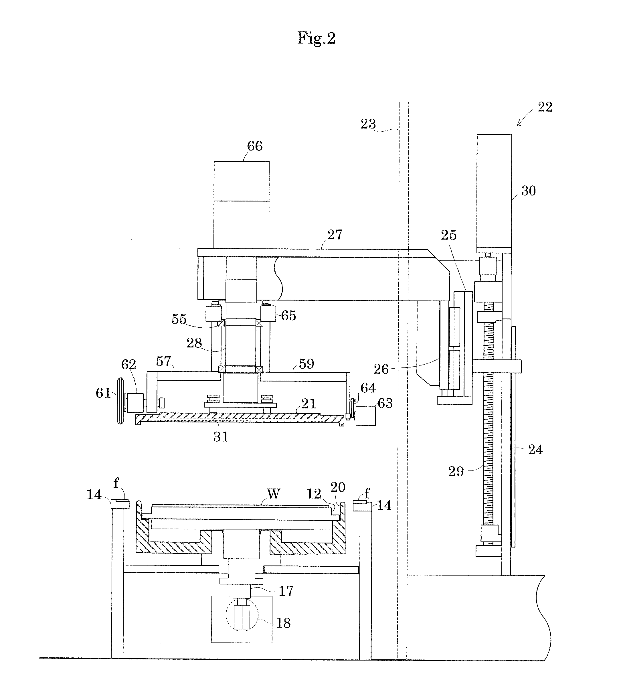
[0038]As shown in FIG. 1, adhesive tape joining apparatus has a tape supply section 1, a separator collecting section 2, a tape joining section 3, and a tape collecting section 4. Description will be given hereinafter of each element in detail.

[0039]As shown in FIG. 1, th...


PUM

PropertyMeasurementUnit
pressureaaaaaaaaaa
atmospheric pressureaaaaaaaaaa
inner pressureaaaaaaaaaa

Abstract

Upper and lower housings nip a supporting adhesive tape that is exposed between an outer periphery of a wafer and a ring frame, thereby forming a chamber. Here, the adhesive tape having a larger width than a diameter of the ring frame divides the chamber into the upper and lower housings to form two spaces. Pressure difference occurs between both spaces such that the lower housing has a reduced pressure than the upper housing for joining the adhesive tape to the wafer.

Description

BACKGROUND OF THE INVENTION[0001]1. Field of the Invention[0002]This invention relates to adhesive tape joining method and apparatus to join a supporting adhesive tape over a rear face of a ring frame and a rear face of a semiconductor wafer placed in a center of the ring frame for integrating the semiconductor wafer with the ring frame via the adhesive tape.[0003]2. Description of the Related Art[0004]Typically, a circuit pattern with numerous components is formed on a surface of a semiconductor wafer (hereinafter simply referred to as a “wafer”), and then a protective tape is joined to the surface of the wafer for protection. Grinding or polishing is performed in a back grinding process to a rear face of the wafer having the protected surface, thereby obtaining a desired thickness of the wafer. The thinned wafer has reduced rigidity, and thus joined to and held on a ring frame via the supporting adhesive tape. Thus, a mount frame is to be manufactured.[0005]A method has been propo...

Claims


Application Information

Patent Timeline
Patent Type & Authority Applications(United States)
IPC IPC(8): B29C65/00B32B38/04
CPCY10T156/12H01L21/67132H01L21/50H01L21/67121H01L2221/68327
Inventor YAMAMOTO, MASAYUKIOKUNO, CHOUHEI
Owner NITTO DENKO CORP
Why Eureka
Try Eureka