Seal with stacked sealing elements

a technology of sealing elements and sealing elements, applied in the field of sealing, can solve the problems of excessive engine vibration, carryover effect, and potential increase in engine vibration, and achieve the effect of effective sealing, enhancing radial deflection of vibration, and preventing rollover of shoes

Active Publication Date: 2011-05-26
SIEMENS ENERGY INC
View PDF34 Cites 64 Cited by
  • Summary
  • Abstract
  • Description
  • Claims
  • Application Information

AI Technical Summary

Benefits of technology

[0012]In the presently preferred embodiment, the hybrid seal comprises at least one shoe extending along one of the rotor and stator in a position to create a non-contact seal therewith. At least one spring element is connected between one of the rotor and stator and the at least one shoe. The spring element(s) is flexible in the radial direction, but axially stiff so that it can function to assist in preventing roll over of the shoes with respect to the rotor or stator where it is located, thus maintaining an effective seal under pressure load. Preferably, stops are provided to limit the extent of radial motion of the shoe with respect to the rotor or stator. The spring elements deflect and move with the shoe(s) in response to the application of fluid pressure to the shoe(s) to create a primary seal, within design tolerances, along the gap between the machine components.
[0013]The shoe(s) is formed with a slot that receives at least two sealing elements which are oriented side-by-side and are connected to one of the first and second machine components. The sealing elements radially deflect and move with the shoe(s) in response to the application of fluid pressure applied to the shoe(s) to assist in the creation of a secondary seal along the gap between the machine components. Preferably, each of the sealing elements comprises an annular plate, which, in alternative embodiments described below, may be formed with structure to enhance the radial deflection thereof. The sealing elements may be formed of sheet metal of varying thickness, or other suitable heat-resistant, flexible material.
[0014]The hybrid seal of this invention can be utilized in all seal applications, including labyrinth, brush and carbon. The robust design eliminates the careful handling now required of carbon seals utilized in lube system compartments. This seal may allow the engine designer to utilize less parts in the assembly as this seal will permit “blind” assemblies to occur.

Problems solved by technology

In addition to increased leakage if clearances are not maintained, such as during a high-G maneuver, there is the potential for increases in engine vibration.
Straight-thru labyrinth seals (FIG. 1A) are the most sensitive to clearance changes, with large clearances resulting in a carryover effect.
Other problems associated with labyrinth seals arise from heat generation due to knife edge to seal land rub, debris from hardcoated knife edges or seal lands being carried through engine passages, and excessive engine vibration.
When seal teeth rub against seal lands, it is possible to generate large amounts of heat.
This heat may result in reduced material strength and may even cause destruction of the seal if heat conducted to the rotor causes further interference.
Other difficulties with hardcoated knife edges include low cycle fatigue life debits, rub induced tooth-edge cracking, and the possibility of handling damage.
As mentioned previously, this vibration can be caused by improper maintenance of radial clearances.
However, it can also be affected by the spacing of labyrinth seal teeth, which can produce harmonics and result in high vibratory stresses.
However, with current technology, all brush seals will eventually wear to line on line contact at the point of greatest initial interference.
Although brush seal leakage generally decreases with exposure to repeated pressure loading, incorporating brush seals where extreme pressure loading occurs may cause a “blow over” condition resulting in permanent deformation of the seal wires.
Brush seals have been used in sealing bearing compartments, however coke on the wires may result in accelerated wear and their leakage rate is higher than that of carbon seals.
One additional limitation of brush seals is that they are essentially uni-directional in operation, i.e., due to the angulation of the individual wires, such seals must be oriented in the direction of rotation of the moving element.
Rotation of the moving element or rotor in the opposite direction, against the angulation of the wires, can result in permanent damage and / or failure of the seal.

Method used


Image

  • Seal with stacked sealing elements
  • Seal with stacked sealing elements
  • Seal with stacked sealing elements

Examples


Embodiment Construction

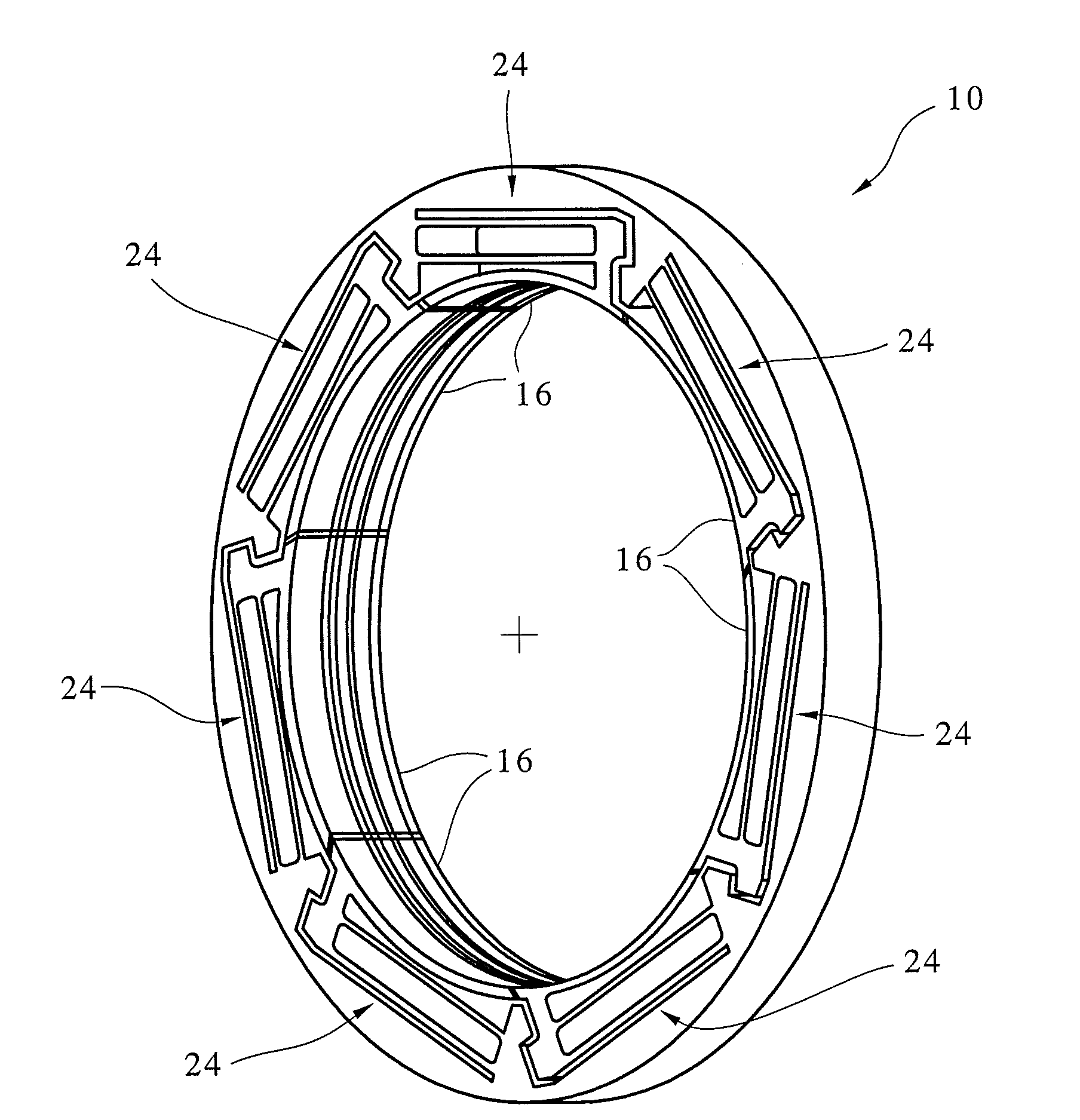
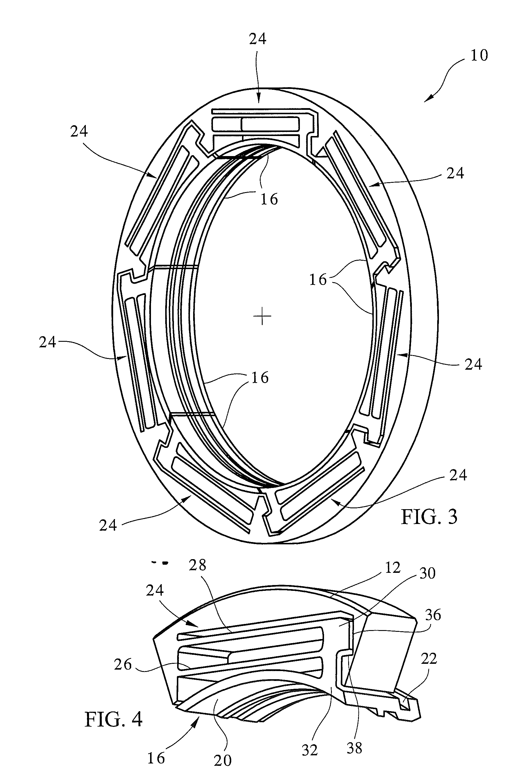
[0029]Referring now to FIGS. 3-6, the hybrid seal 10 of this invention is intended to create a seal of the circumferential gap 11 between two relatively rotating components, namely, a fixed stator 12 and a rotating rotor 14. The seal 10 includes at least one, but preferably a number of circumferentially spaced shoes 16 which are located in a non-contact position along the exterior surface of the rotor 14. Each shoe 16 is formed with a sealing surface 20 and a slot 22 extending radially inwardly toward the sealing surface 20. For purposes of the present discussion, the term “axial” or “axially spaced” refers to a direction along the longitudinal axis of the stator 12 and rotor 14, e.g. axis 18 shown in FIGS. 3 and 6, whereas “radial” refers to a direction perpendicular to the longitudinal axis 18.

[0030]Under some operating conditions, particularly at higher pressures, it is desirable to limit the extent of radial movement of the shoes 16 with respect to the rotor 14 to maintain toler...


PUM


Abstract

A hybrid seal for sealing the circumferential gap between a first machine component and a second machine component comprises at least one shoe extending along one of the machine components in a position to create a non-contact seal, at least one spring element connected between one of the machine components and the shoe(s) and a stack of sealing elements located within a slot formed in the shoe(s), wherein a primary seal and secondary seal of the circumferential gap is created by the shoe(s) in cooperation with the spring element(s) and sealing elements, respectively.

Description

RELATED APPLICATIONS[0001]This application is a continuation-in-part application of U.S. patent application Ser. No. 11 / 953,099 filed Dec. 10, 2007 which is a continuation-in-part of U.S. patent application Ser. No. 11 / 669,454 filed Jan. 31, 2007 and now U.S. Pat. No. 7,410,173 granted Aug. 12, 2008, which is a continuation-in-part application of U.S. patent application Ser. No. 11 / 226,836 filed Sep. 14, 2005 and now U.S. Pat. No. 7,182,345 granted Feb. 27, 2007, which is a continuation of U.S. patent application Ser. No. 10 / 832,053 filed Apr. 26, 2004, now abandoned, which claims the benefit of U.S. Provisional Application Ser. No. 60 / 466,979 filed May 1, 2003 now expired, under 35 U.S.C. §119(e) for all commonly disclosed subject matter. U.S. Provisional Application Ser. No. 60 / 466,979 is expressly incorporated herein by reference in its entirety to form part of the present disclosure.FIELD OF THE INVENTION[0002]This invention relates to seals for sealing a circumferential gap bet...

Claims


Application Information

Patent Timeline
Patent Type & Authority Applications(United States)
IPC IPC(8): F16J15/447
CPCF16J15/442F01D11/025
Inventor JUSTAK, JOHN F.
Owner SIEMENS ENERGY INC
Why Eureka
Try Eureka