Single-antenna fm/cw marine radar

a single-antenna, marine radar technology, applied in the direction of antennas, linear waveguide fed arrays, antenna adaptation in movable bodies, etc., can solve the problems of high cost of navico systems, failure to generate ultra-linear frequency modulation with exceptionally low phase noise, and great difficulty in dealing with exceptionally short ranges of a few feet within confines, etc., to achieve the effect of improving the probability of detection at sea

Active Publication Date: 2011-05-26
NAVICO HLDG
View PDF27 Cites 35 Cited by
  • Summary
  • Abstract
  • Description
  • Claims
  • Application Information

AI Technical Summary

Benefits of technology

[0014]The frequency diversity of the FM / CW radar is also exceptionally valuable to improving probability of detection at sea.

Problems solved by technology

Present day marine radars are very high-powered systems that transmit many kilowatts of peak power and have great difficulty in dealing with exceptionally short ranges of a few feet within the confines of river channels and locks, in addition to providing fine range resolution at ranges of many nautical miles.
The Navico system is expensive because it uses two antennas with transmitter electronics on the back of the transmit antenna and receiver electronics on the back of the receive antenna.
Navico fails to generate an ultra-linear Frequency Modulation with exceptionally low phase noise.
Navico fails to recognize that a sawtooth waveform will cause several problems for the signal processing system.
Navico also fails to recognize that the antenna VSWR must be better than 1.2:1 across the operating frequency band and that there is a critical need to provide a means to cancel the phase noise of the transmitter in the receiver mixer by carefully designed circuit timing delay.

Method used


Image

  • Single-antenna fm/cw marine radar
  • Single-antenna fm/cw marine radar
  • Single-antenna fm/cw marine radar

Examples


Embodiment Construction

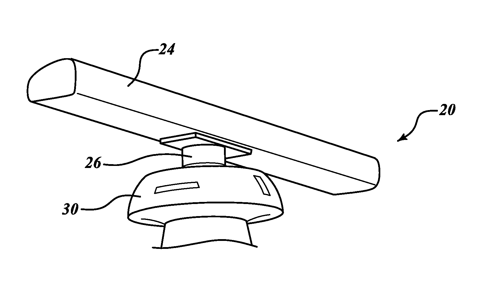
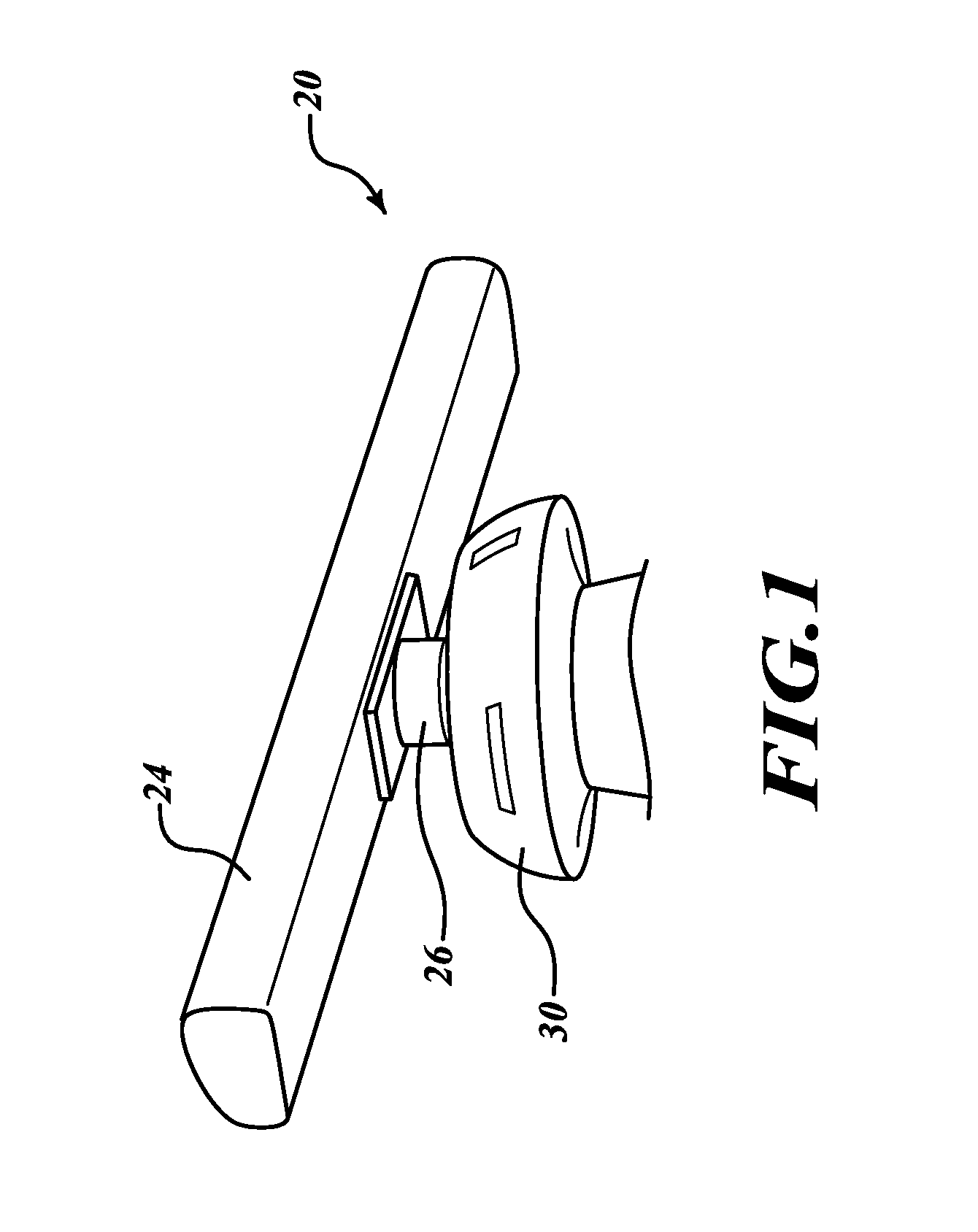
[0022]FIG. 1 is a perspective view of an exemplary single antenna radar device 20. The radar device 20 includes a motor case mounting base 30, an antenna radome 24, and a waveguide rotary joint 26. The waveguide rotary joint 26 allows the antenna radome 24 to rotate about the base 30.

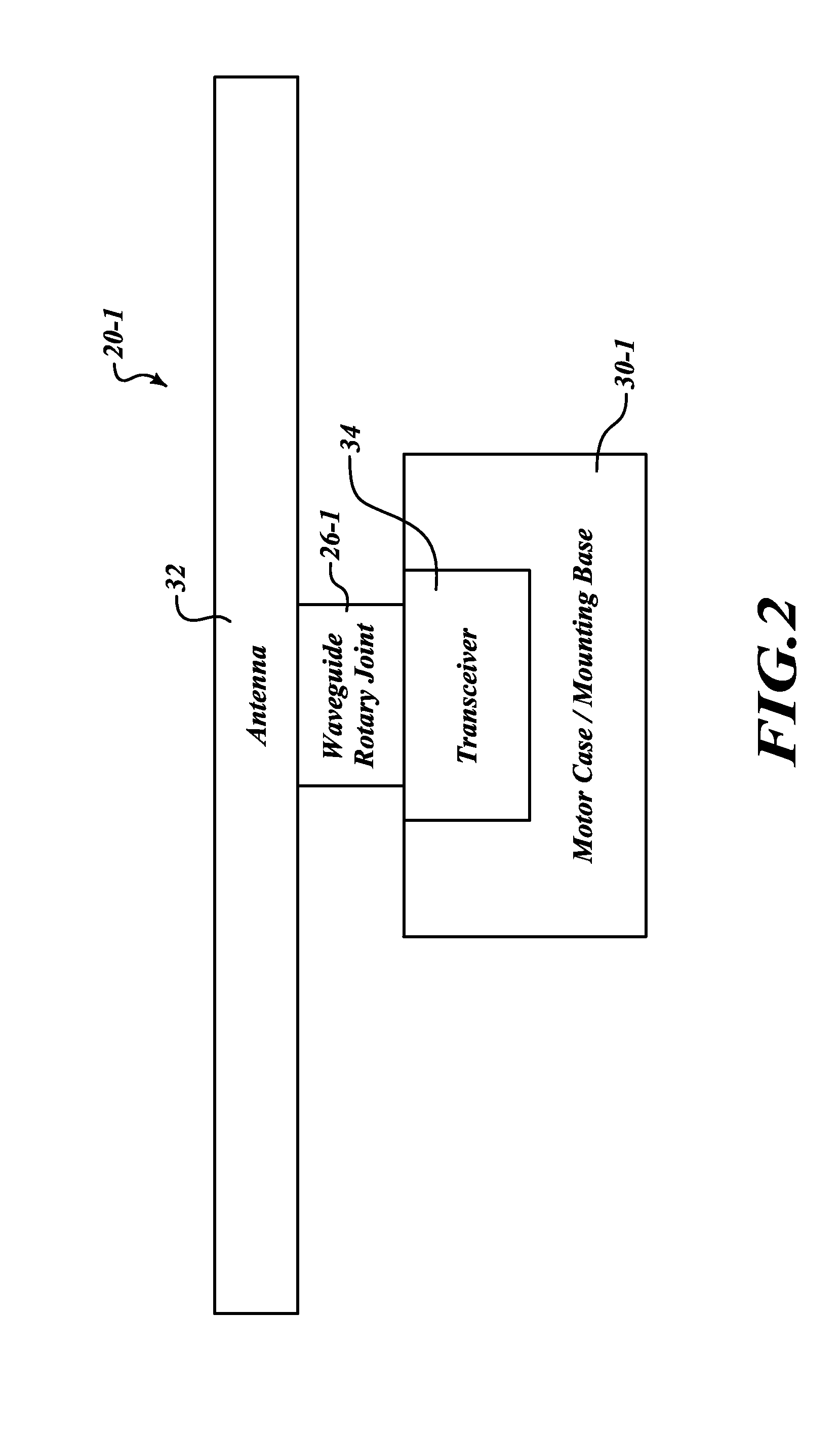
[0023]In one embodiment, the rotary joint 26 provides data and power connections between the base 30 and a single antenna (not shown) within the antenna radome 24. In one embodiment, data transfer includes one or more of capacitive, fiber optic, or inductive transfer. The size and gearing on the rotary joint 26 are selected to provide adequate wind- and shock-loading protection. In the preferred embodiment, the rotary joint 26 is a waveguide rotary joint that conducts the transmitted signal to the antenna (located within the radome 24), receives signals from the antenna and supplies the received signal to the receiver as shown in FIG. 2.

[0024]The single antenna is used for both transmit and receive mode...


PUM


Abstract

A high resolution, low power marine radar for use in applications such as the newly mandated barge/river radars that are to be used in very confined spaces such as canals. An example radar system includes frequency-modulated/continuous-wave (FM/CW) radar that uses very low transmitter power (a fraction of a watt) and has an exceptionally short sensing range of a few feet or even inches if needed.

Description

PRIORITY CLAIM[0001]This application claims priority to U.S. Provisional Application Ser. No. 61 / 263,744 filed on Nov. 23, 2009, the contents of which are hereby incorporated by reference.BACKGROUND OF THE INVENTION[0002]Present day marine radars are very high-powered systems that transmit many kilowatts of peak power and have great difficulty in dealing with exceptionally short ranges of a few feet within the confines of river channels and locks, in addition to providing fine range resolution at ranges of many nautical miles.[0003]Navico provides a frequency modulated / continuous wave (FM / CW) radar for commercial marine radar applications. The actual waveform used by Navico is a single sawtooth having a 10% or higher duty cycle. Their system also uses separate transmit and receive antennas to provide isolation. The Navico system is expensive because it uses two antennas with transmitter electronics on the back of the transmit antenna and receiver electronics on the back of the recei...

Claims


Application Information

Patent Timeline
Patent Type & Authority Applications(United States)
IPC IPC(8): G01S13/00G01S13/937
CPCG01S7/032G01S7/038G01S7/354G01S13/345G01S13/9307H01Q1/34H01Q1/42H01Q3/04H01Q21/005G01S13/937
Inventor VACANTI, DAVID C.
Owner NAVICO HLDG
Why Eureka
Try Eureka