
Modifying Perspective of Stereoscopic Images Based on Changes in User Viewpoint

a stereoscopic image and user viewpoint technology, applied in the field of three-dimensional workstation systems, can solve problems such as image distortion, insufficient communication between objects and within environments, and the dilemma of how to accurately represent the three-dimensional world in which the user lived, so as to minimize viewer discomfort and distortion

Active Publication Date: 2011-05-26
INFINITE Z
View PDF99 Cites 49 Cited by
  • Summary
  • Abstract
  • Description
  • Claims
  • Application Information

AI Technical Summary

Benefits of technology

[0013]The present invention discloses a horizontal perspective workstation employing a horizontal perspective display with a computer system. The personal computer is perfectly suitable for horizontal perspective display since it is designed for the operation of one person, and the computer, with its powerful microprocessor, is well capable of rendering various horizontal perspective images to the viewer. Further, horizontal perspective offers open space display of 3D images, thus allowing the hands-on interaction of end users. Together with binaural or three dimensional audio, the horizontal perspective workstation can offer a realistic simulation of reality. Furthermore, with the addition of user biofeedback, the horizontal perspective workstation can also tailor the simulation to suit a particular user.
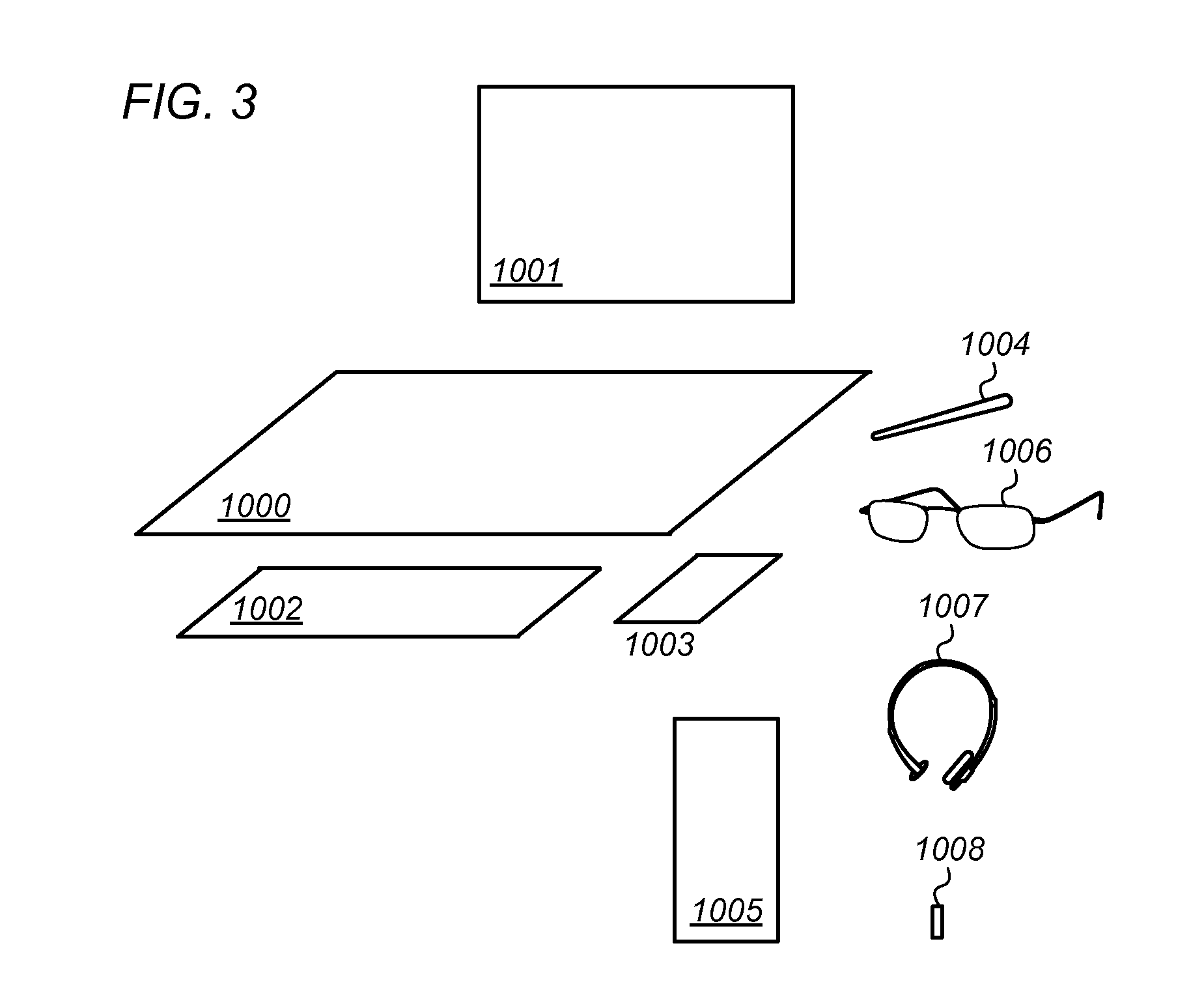
[0015]The horizontal perspective workstation further comprises a computer system with standard peripheral devices such as a keyboard, a mouse, a trackball, a stylus, a tablet, a camera, a scanner, or a printer. The connections can be wired or wireless. The positions of these peripheral devices are flexible and usually arranged for achieving the user's support and comfort.
[0018]Further, the horizontal perspective workstation can comprise curvilinear blending display surfaces to merge the various images. The horizontal perspective workstation can adjust the images to accommodate the position of the viewer. By changing the displayed images to keep the camera eyepoint of the horizontal perspective and central perspective images in the same position as the viewer's eyepoint, the viewer's eye is always positioned at the proper viewing position to perceive the three dimensional illusion, thus minimizing the viewer's discomfort and distortion. The display can accept manual input such as a computer mouse, trackball, joystick, tablet, etc. to re-position the horizontal perspective images. The display can also automatically re-position the images based on an input device automatically providing the viewer's viewpoint location. The horizontal perspective workstation can provide a simulator system by allowing the user to manipulate the images with hands or hand-held tools.

Problems solved by technology

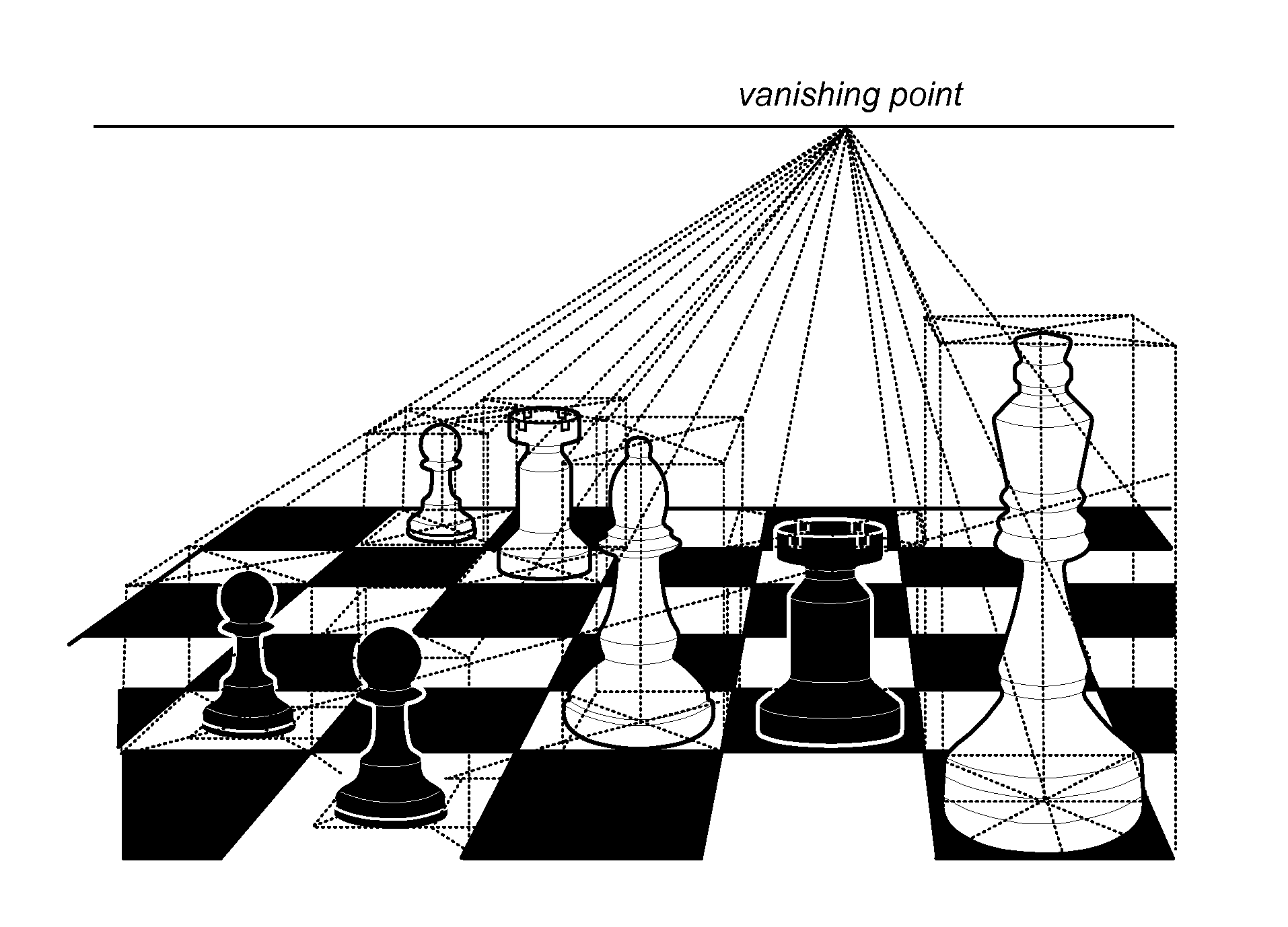
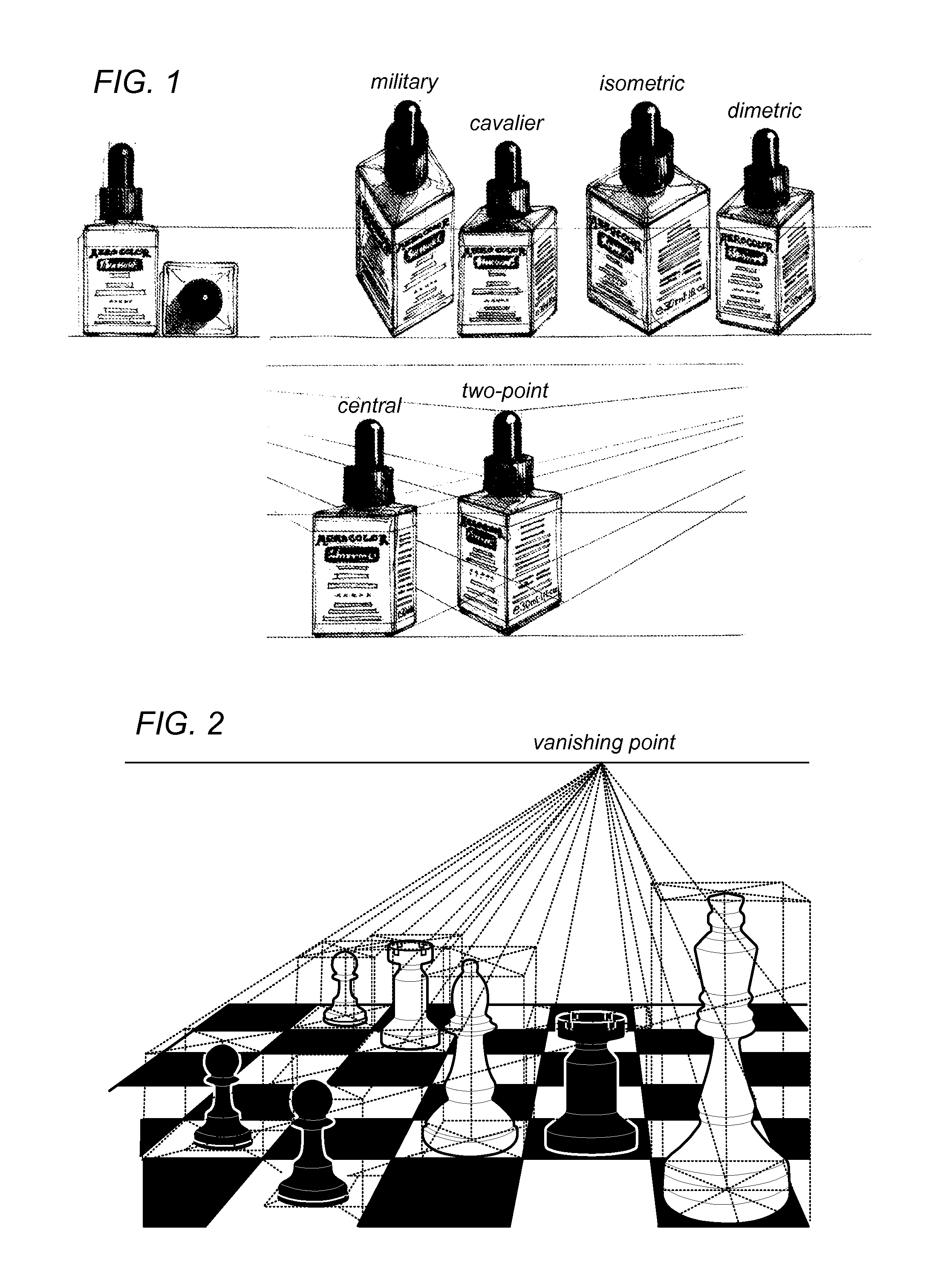
Ever since humans began to communicate through pictures, they faced a dilemma of how to accurately represent the three-dimensional world they lived in.
Sculpture was used to successfully depict three-dimensional objects, but was not adequate to communicate spatial relationships between objects and within environments.
Viewing the images at an angle different from 90° would result in image distortion, meaning a square would be seen as a rectangle when the viewing surface is not perpendicular to the line of vision.
Horizontal perspective images offer realistic three dimensional illusions, but are little known primarily due to the narrow viewing location (the viewer's eyepoint has to coincide precisely with the image projection eyepoint) and the complexity involved in projecting the two dimensional image or the three dimension model into the horizontal perspective image.
Further, with much experience in viewing three dimensional depth cues from perpendicular images, viewers can tolerate a significant amount of distortion generated by the deviations from the camera point.
In contrast, the creation of a horizontal perspective image does require much manipulation.
Making a horizontal drawing requires much effort and is very time consuming.

Method used


Image

  • Modifying Perspective of Stereoscopic Images Based on Changes in User Viewpoint
  • Modifying Perspective of Stereoscopic Images Based on Changes in User Viewpoint
  • Modifying Perspective of Stereoscopic Images Based on Changes in User Viewpoint

Examples


Embodiment Construction

Terms

[0033]The following is a list of terms used in the present application:

[0034]Memory Medium—any of various types of memory devices or storage devices. The term “memory medium” is intended to include an installation medium, e.g., a CD-ROM, floppy disks 104, or tape device; a computer system memory or random access memory such as DRAM, DDR RAM, SRAM, EDO RAM, Rambus RAM, etc.; a non-volatile memory such as a Flash, magnetic media, e.g., a hard drive, or optical storage; registers, or other similar types of memory elements, etc. The memory medium may comprise other types of memory as well or combinations thereof. In addition, the memory medium may be located in a first computer in which the programs are executed, or may be located in a second different computer which connects to the first computer over a network, such as the Internet. In the latter instance, the second computer may provide program instructions to the first computer for execution. The term “memory medium” may includ...


PUM


Abstract

Modifying perspective of stereoscopic images provided by one or more displays based on changes in user viewpoint. The one or more displays may include a first display that is provided substantially horizontal for displaying 3D horizontal perspective images and / or a second display that is provided substantially vertical for displaying text or conventional images such as 2D images, or 3D vertical perspective images. The horizontal display surface may be typically positioned directly in front of the user, and at a height of about a desktop surface so that the user can have about a 45° looking angle. The vertical display surface may be positioned in front of the user and preferably behind and above the horizontal display surface.

Description

PRIORITY INFORMATION[0001]This application is a Continuation in Part of U.S. patent application Ser. No. 11 / 429,829, entitled “Three Dimensional Horizontal Perspective Workstation”, which claims priority to U.S. provisional application Ser. No. 60 / 679,633, filed May 9, 2005, entitled “Three dimensional horizontal perspective workstation”, both of which are incorporated by reference in their entirety as though fully and completely set forth herein.FIELD OF THE INVENTION[0002]This invention relates to a three-dimensional workstation system, and in particular, to a multiple monitor hands-on computer simulator system capable of operator interaction.DESCRIPTION OF THE RELATED ART[0003]Three dimensional (3D) capable electronics and computing hardware devices and real-time computer-generated 3D computer graphics have been a popular area of computer science for the past few decades, with innovations in visual, audio, tactile and biofeedback systems. Much of the research in this area has pro...

Claims


Application Information

Patent Timeline
IPC IPC(8): G06T15/00
CPCG06T15/20G06T15/06G06T15/30G06T2200/04G06T2215/16
Inventor VESELY, MICHAEL A.CLEMENS, NANCY L.GRAY, ALAN S.
Owner INFINITE Z
Learn More