Diffractive optical element, optical system including the same, and image pickup apparatus

a technology of applied in the field of diffractive optical elements and optical systems, can solve the problems of unsatisfactory reduction effect, grating generation, and unsatisfactory light reduction

Inactive Publication Date: 2011-05-26
CANON KK
View PDF9 Cites 8 Cited by
  • Summary
  • Abstract
  • Description
  • Claims
  • Application Information

AI Technical Summary

Problems solved by technology

On the other hand, a light beam entering a grating side surface of a grating part of a diffraction grating behaves as being reflected or refracted by the grating side surface unlike the case of a grating surface, resulting in undesirable light.
The structure of changing an inclination of the grating side surface so as to reduce light having entered the grating side surface reaching an image plane (evaluation plane) in order that the undesirable light generated by the grating side surface is reduced does not always has a sufficient effect of reduction.
Therefore, it is very difficult to find a combination of multiple optical materials having a sufficient effect among currently used materials.
However, in the structure, the entire grating thickness increases (the grating becomes thick).
Therefore, undesirable light is generated when the light that does not contribute to imaging enters the wall surface (grating side surface), and it becomes very difficult to reduce the generated undesirable light.

Method used


Image

  • Diffractive optical element, optical system including the same, and image pickup apparatus
  • Diffractive optical element, optical system including the same, and image pickup apparatus
  • Diffractive optical element, optical system including the same, and image pickup apparatus

Examples


embodiment 1

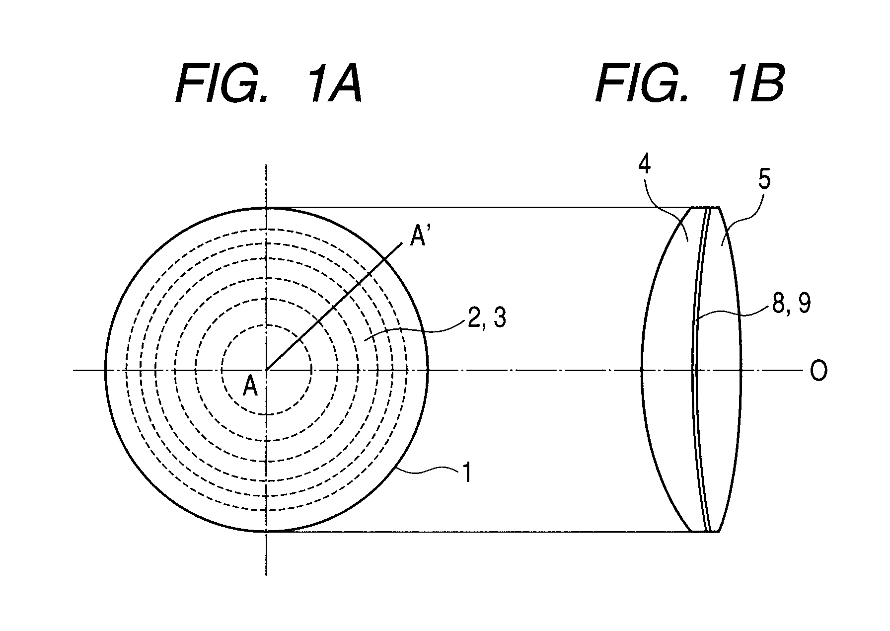
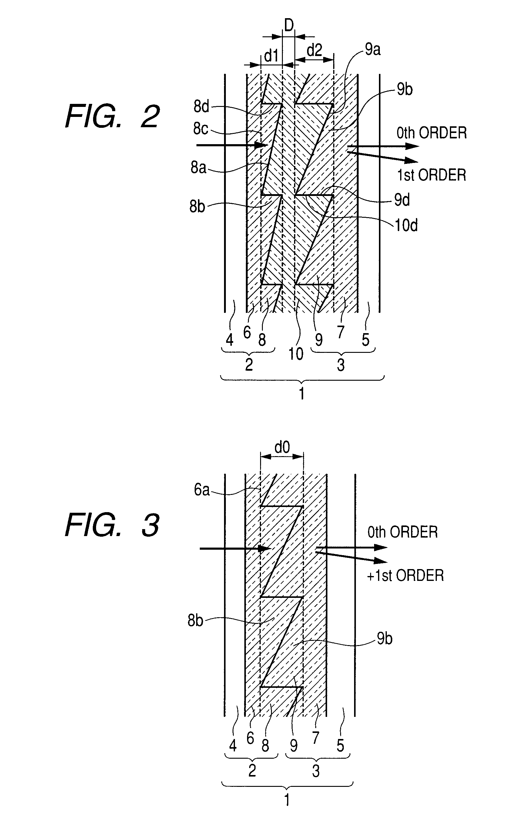
[0072]Next, a specific structure of Embodiment 1 is described. FIG. 1A is a front view of the diffractive optical element according to Embodiment 1 of the present invention, and FIG. 1B is a side view of the diffractive optical element illustrated in FIG. 1A. In addition, FIG. 2 illustrates an enlarged cross sectional view of a part of the diffractive optical element illustrated in FIG. 1A which is viewed from the line A-A′. Note that FIG. 2 is enlargedly deformed in the grating depth direction of the grating part of the diffraction grating. As illustrated in those diagrams, the diffractive optical element 1 has a structure in which the first element part 2 and the second element part 3 are superposed so that the first diffraction grating 8 and the second diffraction grating 9 formed in the element parts 2 and 3 are in intimate contact to each other sandwiching the third material layer 10 therebetween. In addition, as illustrated in FIG. 2, the first element part 2 includes the firs...

embodiment 2

[0087]As for the RCWA calculation result when the light (+10 degrees) other than the light beam used for imaging enters the diffractive optical element 1, the light having a wavelength of 650 nm causes more undesirable light in Embodiment 1 than in the reference example. This is due to the slight difference in refractive index between the second material forming the diffraction grating 9 and the third material layer 10. FIG. 9 is a cross sectional view of a main part of the diffractive optical element according to Embodiment 2 of the present invention. The structure illustrated in FIG. 9 has the same material and shape as that of Embodiment 1, which includes the diffraction grating 8 made of the first material (M2B) and the diffraction grating 9 made of the second material (M1A, M2A). Further, the material (M1B) forming the third material layer (third diffraction grating) 10 is also the same as in Embodiment 1. The first diffraction grating 9 and the third material layer 10 correspo...

embodiment 3

[0092]Embodiment 2 described above has the structure in which the second diffraction grating 9 and the third material layer 10 with a small refractive index difference are cemented in intimate contact so as to sandwich the grating surface 9a, but the diffractive optical element of the present invention is not limited to this structure. FIG. 11 is a cross sectional view of a main part of the diffractive optical element 1 according to Embodiment 3 of the present invention. The diffractive optical element 1 according to Embodiment 3 is obtained by reversing the first diffraction grating 8 and the third material layer 10 of the diffractive optical element according to Embodiment 2. In the diffractive optical element 1 illustrated in FIG. 11, a resin (Nd=1.564, νd=20.8) in which ITO microparticles were mixed in an ultraviolet curing resin manufactured by DIC Corporation was used for the first diffraction grating (M1B) 8 and the base part 6. On the other hand, a resin (Nd=1.569, νd=47.9) ...


PUM


Abstract

A diffractive optical element includes multiple diffraction gratings laminated and made of at least three material types, wherein the multiple diffraction gratings include: a first combination part including two diffraction gratings of materials different from each other in which grating side surfaces of grating parts contact with each other or are disposed close to each other in a grating pitch direction; and a second combination part including two diffraction gratings of materials different from each other in which at least one material is different from the materials of the first combination part; and when N1Aw and N1Bw denote refractive indices of the first combination part at a wavelength (w), ν1A and ν1B denote Abbe numbers, N2Ad and N2Bd denote refractive indices of the second combination part on a d-line, ν2A and ν2B denote Abbe numbers, the wavelength (w) is 370<w<730 (nm). The followings are satisfied:N1Aw−N1Bw=0;16<(ν1A−ν1B)<75;0.03<|N2Ad−N2Bd|<0.5; and16<(ν2A−ν2B)<75.

Description

BACKGROUND OF THE INVENTION[0001]1. Field of the Invention[0002]The present invention relates to a diffractive optical element and an optical system including the same, which is used as an optical system of optical equipment such as a video camera, a digital camera, and a television camera.[0003]2. Description of the Related Art[0004]As a method of reducing chromatic aberration of an optical system (lens system), there is known a method of combining different glass materials. Other than that, there is known a method of disposing a diffractive optical element having a diffraction action in a part of the optical system. It is known that the diffractive optical element is provided with an effect of chromatic aberration correction as well as an effect of an aspheric lens by changing a period of its periodical structure appropriately. Here, one light beam is still one light beam after being refracted, while one light beam is split into light beams of individual orders after being diffrac...

Claims


Application Information

Patent Timeline
Patent Type & Authority Applications(United States)
IPC IPC(8): H04N5/335G02B5/18
CPCG02B5/1847G02B5/1866G02B27/4211H04N5/2254G02B5/1814G02B27/0037
Inventor KOBAYASHI, MIKIO
Owner CANON KK
Why Eureka
Try Eureka