Method and system for analyzing and qualifying routes in packet networks

Active Publication Date: 2011-05-26
MICROSEMI FREQUENCY & TIME
View PDF5 Cites 49 Cited by
  • Summary
  • Abstract
  • Description
  • Claims
  • Application Information

AI Technical Summary

Benefits of technology

[0021]In addition, if a slave has access to two or more masters, the techniques according to embodiments of the invention can be used to identify which is the better master. Similarly, if two or more slaves have a path to one master, the techniques according to embodiments of the invention can be used to identify congestion in the portion of the network that is not common to the paths between the slaves and the master. Furthermore, by having “shadow slaves” distributed over the network, the techniques according to embodiments of the invention can be used to generate a congestion map, allowing the network operator to identify, in real-time, parts of the network that are congested and thereby take appropriat

Problems solved by technology

Using GPS signals to achieve time or frequency alignment is generally quite expensive and requires a client system to be able to receive the radio frequency (RF) signals from GPS satellites.
While frequency alignment within conventional TDM networks is relatively straightforward, packet networks, such as networks based on the popular Ethernet industry standards, present time and frequency alignment challenges because packet networks are not conventionally designed to provide precise delivery time for data or precise timing at any lower protocol levels.
Furthermore, packet networks typically involve multiple nodes that may store and forward data packets, potentially introducing significant transit delay variation between any two points.
However, conventional networks typically have a wide range of bandwidth loading conditions, which leads to large transit delay variations.
This transit delay variation typically leads to degradation of time alignment accuracy.
Furthermore, network elements comprising the packet network may process sequential packets differently, depending on prevailing congestion conditions that result from increased bandwidth loading within the network.
Once the congestion threshold is exceeded, the network el

Method used


Image

  • Method and system for analyzing and qualifying routes in packet networks
  • Method and system for analyzing and qualifying routes in packet networks
  • Method and system for analyzing and qualifying routes in packet networks

Examples


Embodiment Construction

[0029]In the following description, numerous specific details are set forth to provide a more thorough understanding of the invention. However, it will be apparent to one of skill in the art that the invention may be practiced without one or more of these specific details. In other instances, well-known features have not been described in order to avoid obscuring the invention.

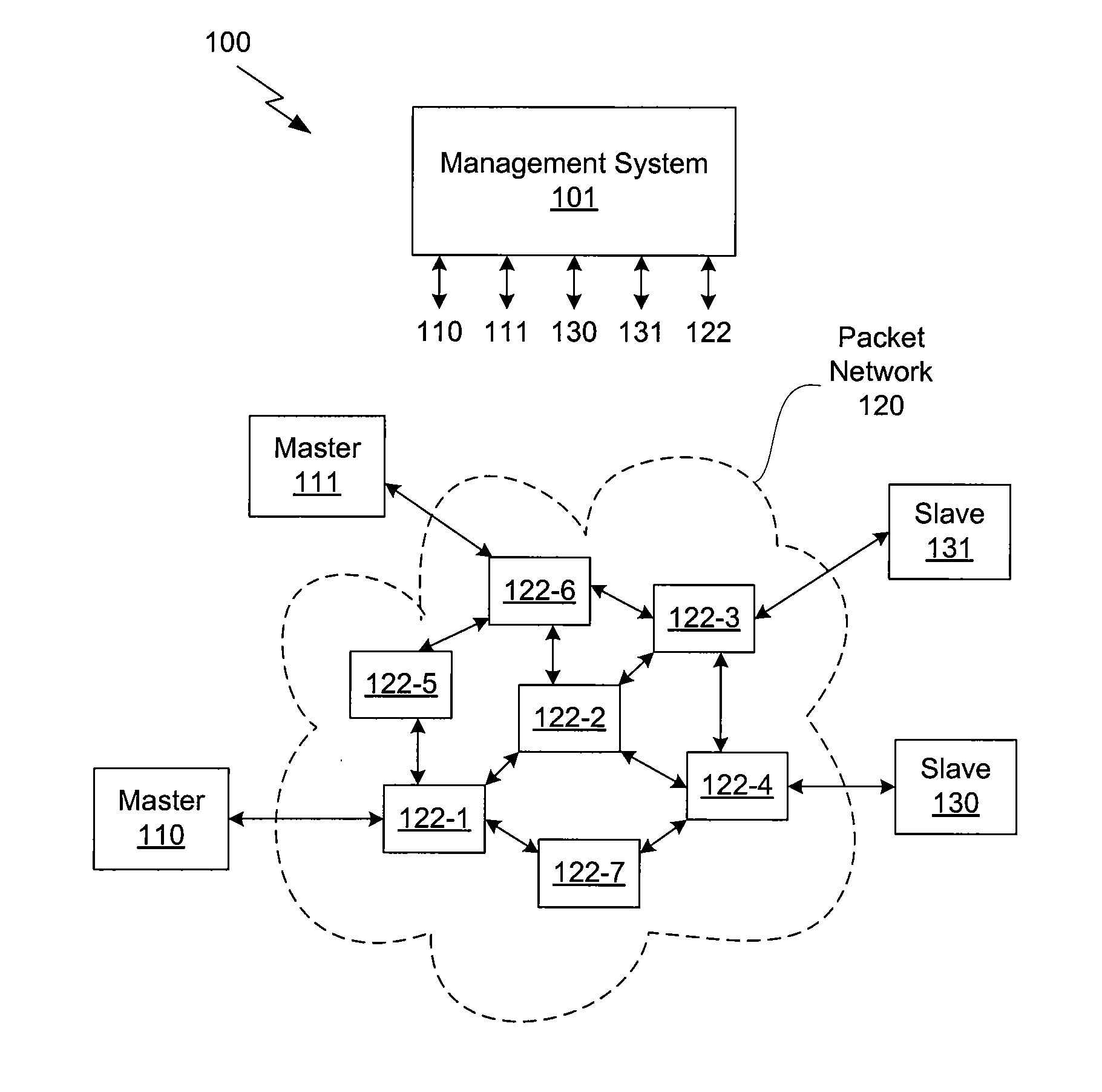
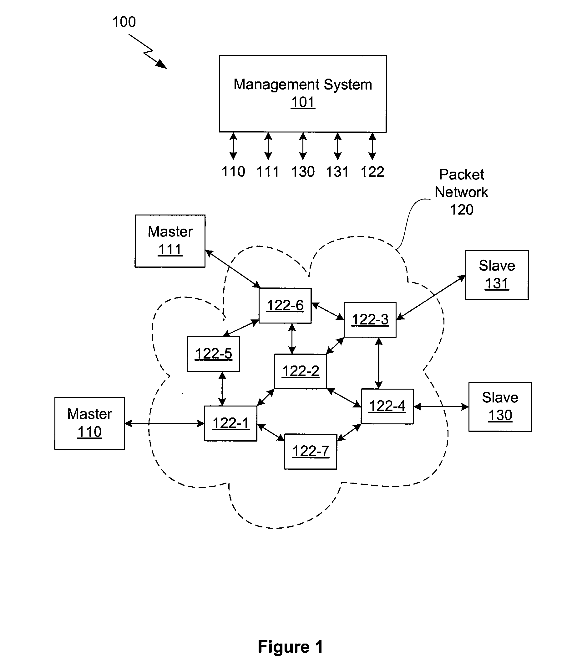
[0030]FIG. 1 illustrates a network system 100 configured to implement one or more aspects of the invention. Network system 100 may include one or more master clocks and one or more slave clocks. In the embodiment illustrated in FIG. 1, network system includes two master clocks, namely master clock 110 and master clock 111, and two slave clocks, slave clock 130 and slave clock 131. The communication path between a master clock and a slave clock is through a packet network 120, which includes a plurality of network elements 122. Network system 100 is managed by a management system 101, which communicates with ea...


PUM


Abstract

Routes of a packet network are analyzed according to various transit delay metrics. Preferred packet network routes are selected between source and destination based on these metrics. In packet networks employing boundary clocks and transparent clocks, faulty boundary clocks and faulty transparent clocks are identified using the metrics.

Description

CROSS-REFERENCE TO RELATED APPLICATIONS[0001]This application claims the benefit of U.S. Provisional Patent Application 61 / 263,264, filed Nov. 20, 2009, and U.S. Provisional Patent Application 61 / 318,170, filed Mar. 26, 2010. Both of the foregoing applications are incorporated by reference herein.BACKGROUND OF THE INVENTION[0002]1. Field of the Invention[0003]Embodiments of the invention relate generally to time and frequency alignment systems operating over digital communications networks and, more specifically, to a method and a system for analyzing and qualifying routes in packet networks.[0004]2. Description of the Related Art[0005]One of the more important requirements of a digital communication network is to support real-time communications applications, which typically require time or frequency alignment, or a combination of both. For example, time alignment may be used by real-time instrumentation systems gathering data at specific time intervals or operating machinery accor...

Claims


Application Information

Patent Timeline
IPC IPC(8): H04J3/06H04L12/56H04L12/26
CPCH04J3/0641H04J3/0682H04L45/121H04L45/00H04L41/082
Inventor ZAMPETTI, GEORGE P.SHENOI, KISHAN
Owner MICROSEMI FREQUENCY & TIME
Why Eureka
Try Eureka