Ultrasonic transducer for use in a fluid medium

a transducer and ultrasonic technology, applied in the field of ultrasonic transducers for use in fluid mediums, can solve the problems of insufficient subsidence, less stability, and difficulty in injecting a sufficient amount of sound energy into the air or receiving it from the air in real air ultrasonic transducers, and achieves high material-intrinsic damping, high modulus of elasticity, and suitable damping

Inactive Publication Date: 2011-05-26
ROBERT BOSCH GMBH
View PDF11 Cites 67 Cited by
  • Summary
  • Abstract
  • Description
  • Claims
  • Application Information

AI Technical Summary

Benefits of technology

[0014]According to example embodiments of the present invention, a method for manufacturing an ultrasonic transducer for use in a fluid medium is provided, in particular an ultrasonic transducer in one or more of the example embodiments illustrated above. At least one transducer core is provided, which includes at least one acoustic / electric transducer element. Furthermore, at least one decoupling element is provided, which is configured to at least reduce a structure-borne noise coupling between the transducer core and a housing, for example a housing of the ultrasonic transducer itself or a further housing into which the ultrasonic transducer is embedded. At least one porous plastic material, in particular a foamed plastic material, is used to manufacture the decoupling element, the porous plastic material including at least one thermosetting polymer and / or at least one thermoplastic.
[0021]The ultrasonic transducer and the method described herein are considered to have numerous advantages over conventional ultrasonic transducers and methods. In particular, parasitic ultrasound paths within the materials of the ultrasonic transducers and / or the housing, in particular a sensor housing, may be substantially reduced, in particular structure-borne noise, which would otherwise corrupt the measuring signal. This makes it possible to prevent the ascertained value for the flow rate to be measured from exceeding the required tolerance limits. At the same time, example embodiments of the present invention provide dimensionally stable suspension of the transducer core. A stress-free and thus permanently media-tight sealing layer may simultaneously be implemented.
[0022]For example, a casting and / or injection process may be used to manufacture the ultrasonic transducer, in particular the decoupling element. Despite the fact that the connection to the transducer core in this case tends to be over a wide area instead of at specific points or in a linear manner, the decoupling may be implemented by the material properties of the decoupling element. In this manner, a suitable damping may be achieved, for example by scattering at the pores of the porous plastic material, for example by an impedance mismatch between the transducer core and the housing. A mismatch of this type may be further supported by selecting largely effective layer thicknesses of the decoupling element along the directions of structure-borne noise propagation such that multiple reflections on the corresponding limiting surfaces which limit the decoupling element interfere with each other in a largely destructive manner. In contrast to silicones, the described porous thermosetting polymers and / or thermoplastics have a relatively high modulus of elasticity, on the one hand, and a high material-intrinsic damping, on the other hand. For example, an adiabatic compression in the cavities may result in improved damping.

Problems solved by technology

Due to the low air impedance, this theoretical value may usually be achieved only with the aid of extremely porous materials, such as aerogels, which, however, are less sturdy.
Due to the impedance matching actually achieved between the piezoelectric member and the air, it is usually difficult to inject a sufficient amount of sound energy into the air or to receive it from the air in real air ultrasonic transducers, as opposed to applications in liquids.
This parasitic sound transfer is usually much stronger that the actual useful signal through the air, and it also usually does not sufficiently subside until the actual useful signal arrives.
A disadvantage of these approaches, however, is a usually insufficient media resistance of the decoupling materials used or of the connecting points between the decoupling material and the adjacent materials.
This is extremely difficult, in light of assembly tolerances of the relatively soft decoupling molded parts.
A mismatch of this type may be further supported by selecting largely effective layer thicknesses of the decoupling element along the directions of structure-borne noise propagation such that multiple reflections on the corresponding limiting surfaces which limit the decoupling element interfere with each other in a largely destructive manner.

Method used


Image

  • Ultrasonic transducer for use in a fluid medium
  • Ultrasonic transducer for use in a fluid medium

Examples


Embodiment Construction

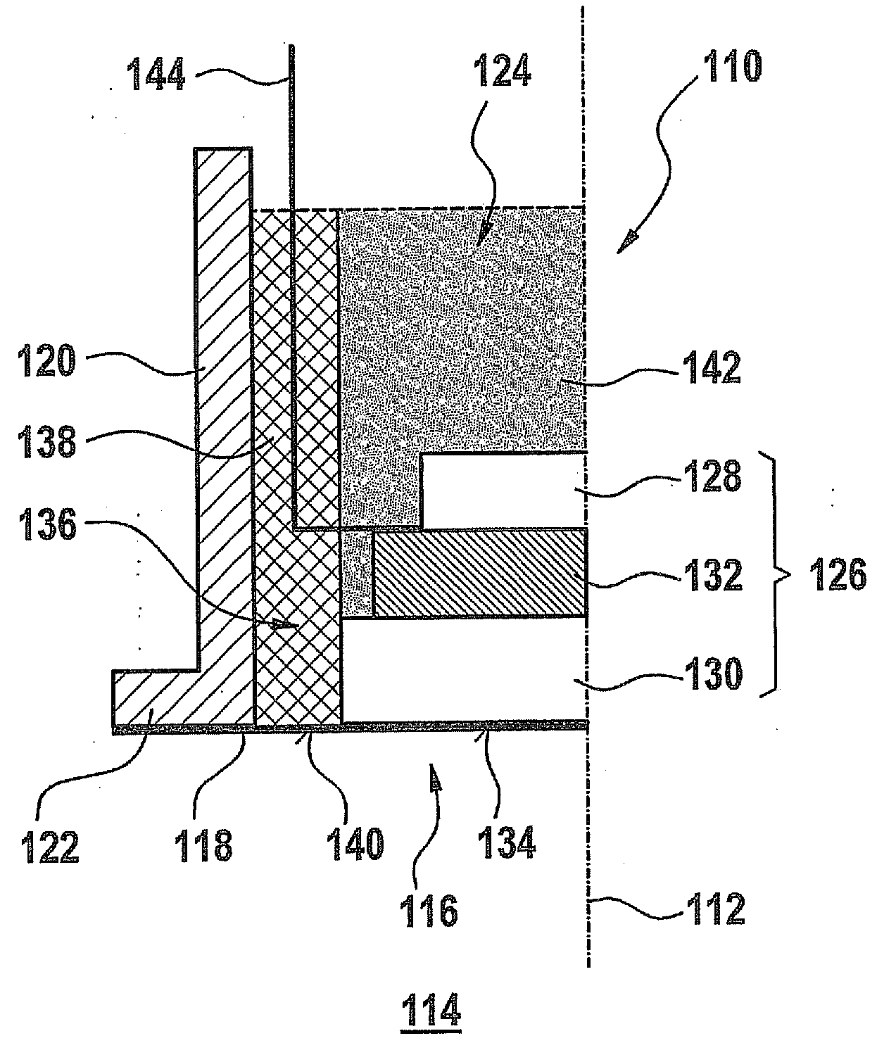
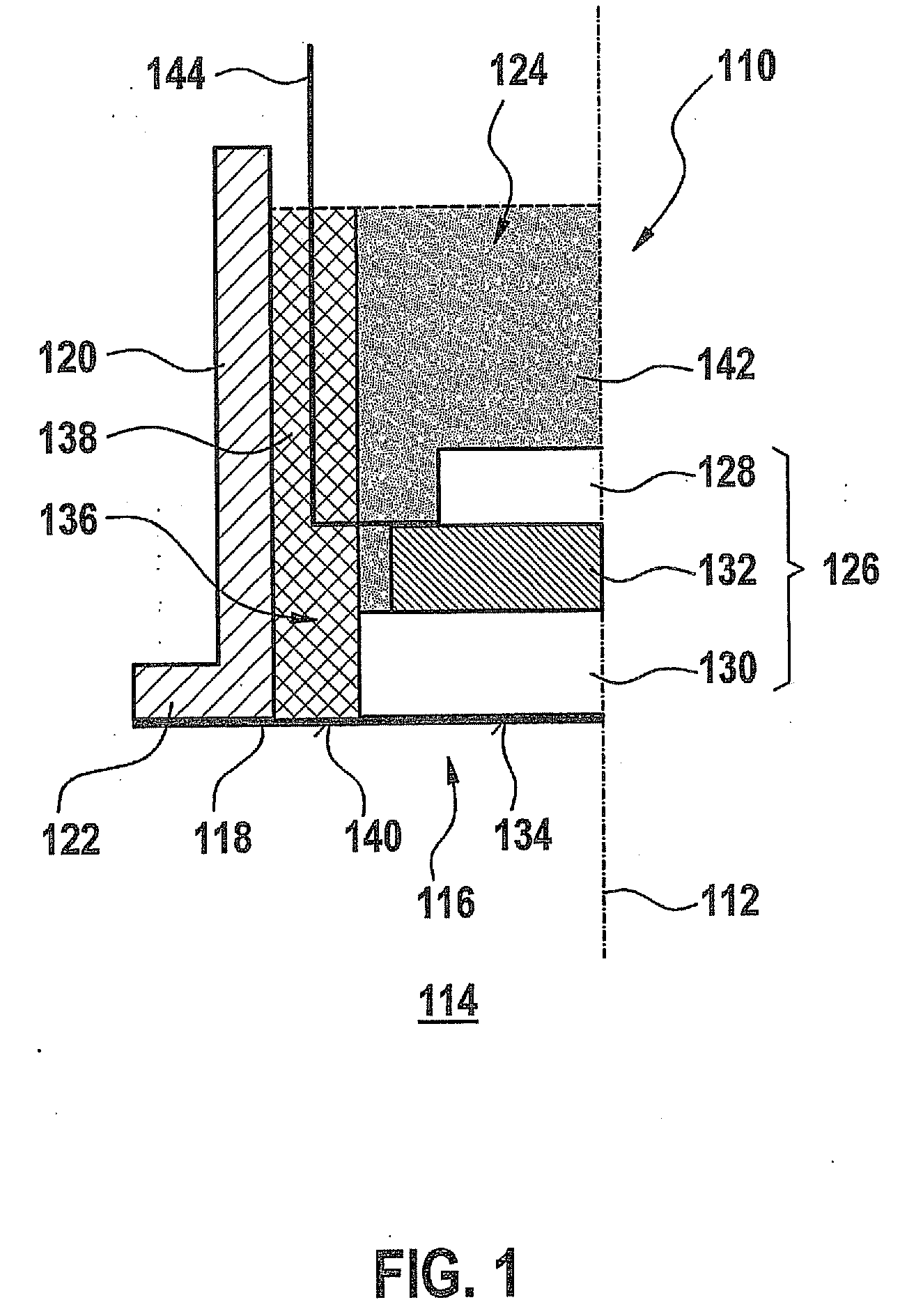
[0027]FIG. 1 shows a sectional representation of an exemplary embodiment of an ultrasonic transducer 110, viewed from the side. In the illustrated exemplary embodiment, ultrasonic transducer 110 is arranged by way of example to be rotationally symmetrical around an axis of symmetry 112, other arrangement also being possible, however. Ultrasonic transducer 110 is provided for use in a fluid medium, for example air, which is identified symbolically by reference numeral 114 in FIG. 1. A front surface 116 of ultrasonic transducer 110 faces fluid medium 114. This front surface 116 may be sealed, for example, by a sealing film 118.

[0028]Ultrasonic transducer 110 includes a housing 120, which may be arranged, for example, as a sleeve. The housing is open toward fluid medium 114 or toward front surface 116 and has an edge 122 facing fluid medium 114. Sealing film 118 may be connected to this edge 122 in an integral manner and / or another manner, for example by gluing.

[0029]A transducer core ...


PUM


Abstract

An ultrasonic transducer for use in a fluid medium includes at least one transducer core having at least one acoustic / electric transducer element. The ultrasonic transducer furthermore includes at least one decoupling element which is configured to reduce a structure-borne noise coupling between the transducer core and a housing. The decoupling element includes at least one porous plastic material, in particular a foamed plastic material. The porous plastic material includes at least one thermosetting polymer and / or at least one thermoplastic.

Description

CROSS-REFERENCE TO RELATED APPLICATIONS[0001]The present application claims priority to Application No. 10 2009 046 145.0, filed in the Federal Republic of Germany on Oct. 29, 2009, which is expressly incorporated herein in its entirety by reference thereto.FIELD OF THE INVENTION[0002]The present application relates to an ultrasonic transducer for use in a fluid medium.BACKGROUND INFORMATION[0003]Certain ultrasonic transducers which may be used to radiate ultrasonic waves into a fluid medium and / or to absorb ultrasonic waves from the fluid medium are conventional. For example, ultrasonic transducers of this type may be used in ultrasonic flowmeters, for example in process engineering and / or in the automotive industry. Examples of ultrasonic transducers are described in German Published Patent Application No. 10 2007 010 500, German Published Patent Application No. 42 30 773, and European Published Patent Application No. 0 766 071.[0004]Certain conventional ultrasonic flowmeters have...

Claims


Application Information

Patent Timeline
Patent Type & Authority Applications(United States)
IPC IPC(8): A61B8/14
CPCG10K11/002G10K2200/11G10K11/006G10K11/004A61B8/4483
Inventor MUELLER, ROLANDHUEFTLE, GERHARDHORSTBRINK, MICHAELLANG, TOBIASRADWAN, SAMIKUENZL, BERNDWANJA, ROLAND
Owner ROBERT BOSCH GMBH
Why Eureka
Try Eureka