Modular Device Holder

a module device and carrier technology, applied in the direction of supporting structure mounting, transportation and packaging, fuselages, etc., can solve the problems of not being able to fully utilize the equipment carrier, not necessarily suitable for other equipment to be subsequently installed, and relatively small equipment blocking the available structural space, so as to achieve the effect of saving as much weight and being easy to manufactur

Inactive Publication Date: 2011-06-02
AIRBUS OPERATIONS GMBH
View PDF28 Cites 28 Cited by
  • Summary
  • Abstract
  • Description
  • Claims
  • Application Information

AI Technical Summary

Benefits of technology

[0007]The equipment carrier according to the invention may have a modular design and therefore can be easily manufactured from standardized components or assemblies. An outer rack can be arranged or supported within the available volume of the vehicle in order to provide a standardized structural space that can be fully utilized and eliminates the need to examine the structural space and identify connecting points during equipment retrofitting. The inner rack, in which several compartments of various sizes can be provided, supplements the outer rack so as to form a complete equipment carrier. The compartments preferably feature inserts (so-called “trays”) for the equipment to be integrated while the rear wall (“backplane”) of the inner rack features connecting points and interfaces, particularly for the electrical supply and for links to data networks or data buses. The equipment carrier is preferably designed in such a way that the outer rack can completely support the loads of the vehicle and of the equipment carrier. The outer rack is preferably supplied in different standard widths in order to realize various configurations for equipment to be installed and to save as much weight as possible by adapting to the required structural space. The inner rack should be adaptable to the requirements of the equipment to be installed and provide the option of installing the equipment in the interior of the inner rack in accordance with customer requirements. The equipment carrier according to the invention furthermore makes it possible to combine different outer racks with one another in a modular fashion such that new standardized structural space can be easily made available for equipment to be subsequently supplemented and this new structural space can be optimally utilized with the aid of inner racks.

Problems solved by technology

In existing solutions of equipment carriers for aircraft, it is disadvantageous that existing equipment carriers are only individually developed for certain equipment and equipment, the type of which is predefined by the configuration of the aircraft, but not necessarily suitable for other equipment to be subsequently installed.
If new equipment or equipment that initially was not provided needs to be integrated into an existing equipment carrier, this results in, for example, relatively small equipment blocking the available structural space, but simultaneously not fully utilizing the equipment carrier.
Consequently, an oversized equipment carrier with a weight higher than necessary is transported along with the aircraft for a long operating time.
All things considered, conventional equipment carriers cannot be flexibly utilized for accommodating equipment of different structural shapes and sizes.

Method used


Image

  • Modular Device Holder
  • Modular Device Holder
  • Modular Device Holder

Examples


Embodiment Construction

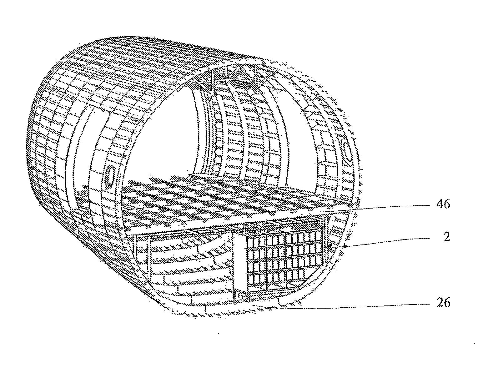
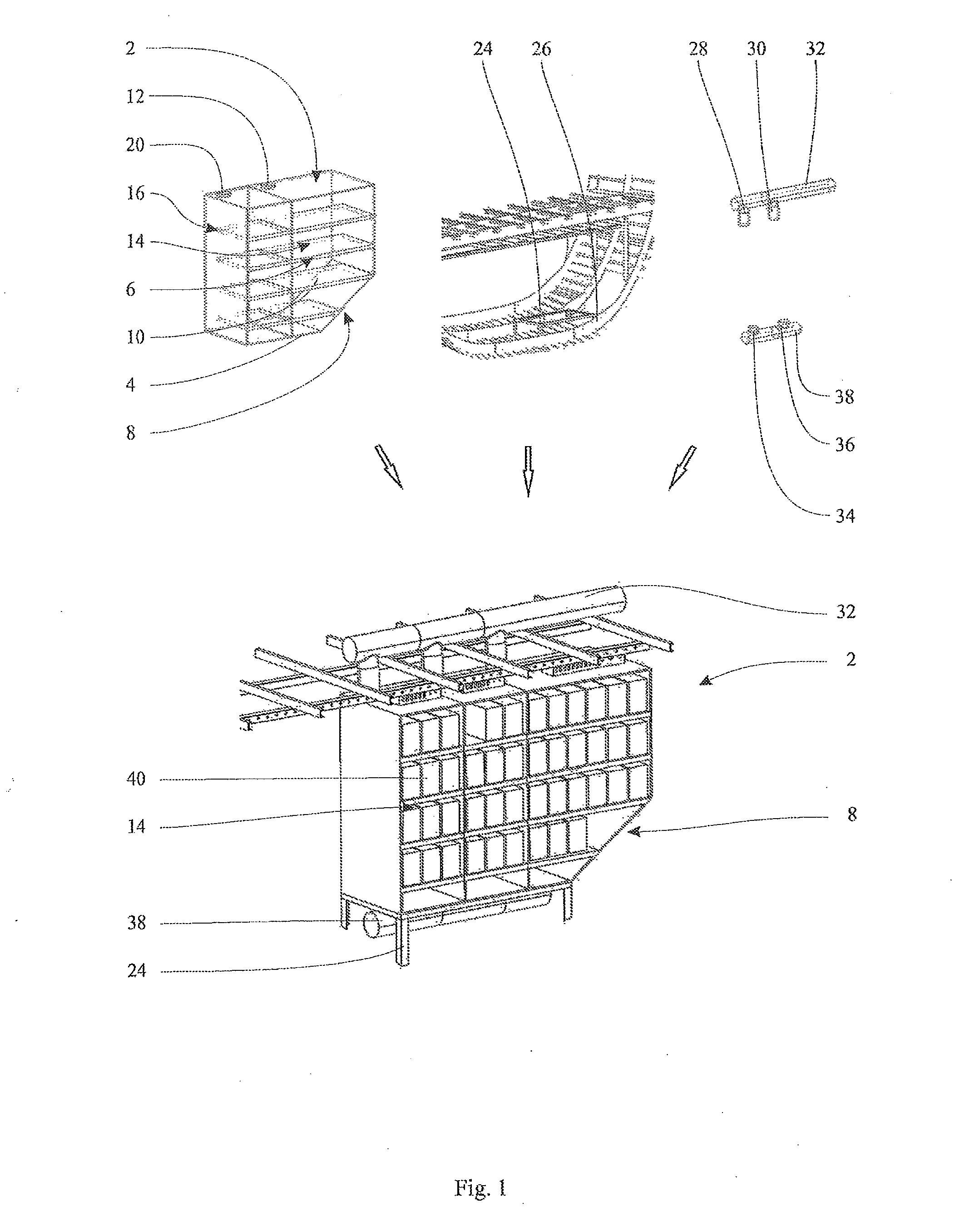
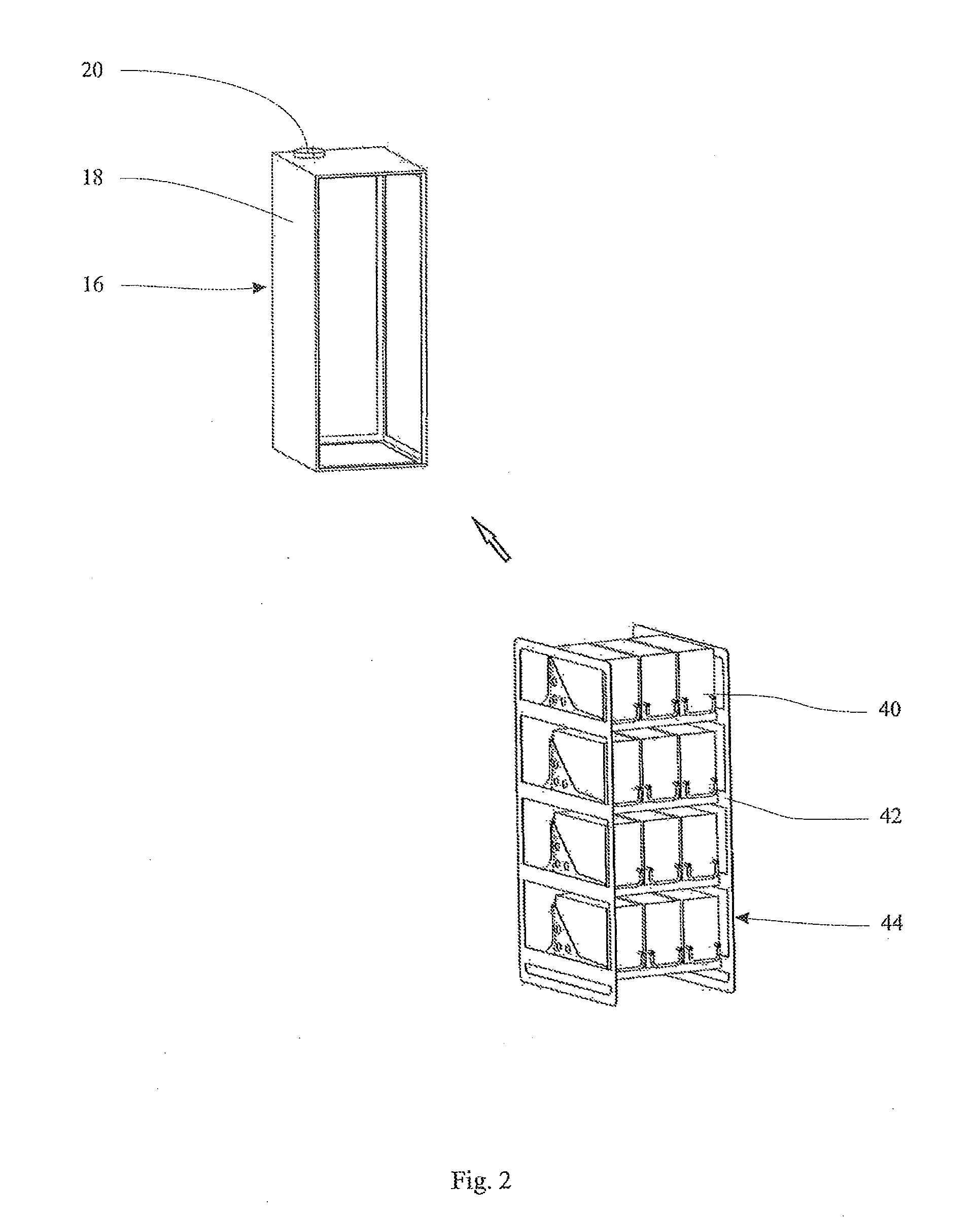
[0016]The basic design of an equipment carrier according to the invention is illustrated in FIG. 1. The equipment carrier 2 according to the invention features an outer rack 4, into which an inner rack 6 can be installed. The racks 4 and 6 are illustrated in the form of exemplary frame racks with an at least partially cased frame structure. For example, the outer rack 4 is beveled on a lower corner 8—as illustrated in FIG. 1—such that it can be laterally installed, for example, into the cargo area of an aircraft that features slanted lower wall regions. Consequently, the outer frame rack 4 can optimally utilize the space provided in a cargo area and simultaneously provide in its interior compartments 14 that are standardized or individually assembled by means of the inner frame rack 6 and serve for accommodating equipment to be integrated.

[0017]The equipment in question that, for example, serves for handling data-processing applications such as on-board entertainment (“in-flight ent...


PUM


Abstract

The invention relates to a device holder for mounting devices in a vehicle. Said device holder comprises at least one external rack and at least one internal rack. The at least one external rack can be mounted on the vehicle structure and has a storage space that is designed to introduce and releasably attach the at least one internal rack. The internal rack has means for forming at least one compartment that has a variable size in order to introduce and mount at least one device. The device holder according to the invention can be particularly well adjusted to the devices that are to be integrated into the vehicle, can optimally utilize the available space, and can be equipped with user-specific devices in standard racks.

Description

REFERENCE TO RELATED APPLICATIONS[0001]This application claims the benefit of the filing date of U.S. Provisional Patent Application No. 61 / 066,969 filed Feb. 25, 2008, and of German Patent Application No. 10 2008 011 026.4 filed Feb. 25, 2008, the disclosure of which applications is hereby incorporated herein by reference.FIELD OF THE INVENTION[0002]The invention pertains to an equipment carrier for mounting equipment in a vehicle.TECHNOLOGICAL BACKGROUND OF THE INVENTION[0003]In modern vehicles such as, for example, passenger aircraft, there is an increasing trend to install technical equipment that does not contribute to the actual operability of the vehicle, but rather fulfills other functions. This equipment may consist, for example, of on-board entertainment or communications equipment. Equipment of this type is usually installed into designated equipment carriers that are arranged at special preferred installation points within the vehicle. In passenger aircraft, for example,...

Claims


Application Information

Patent Timeline
Patent Type & Authority Applications(United States)
IPC IPC(8): B64C1/22B60R11/00
CPCH05K7/1412B64C1/18
Inventor JAGER, HARTWIGROHLFS, GERDBARTELS, BENJAMINLUEDEMANN, OLAF
Owner AIRBUS OPERATIONS GMBH
Why Eureka
Try Eureka