
Computed tomography method, computer software, computing device and computed tomography system for determining a volumetric representation of a sample

a computed tomography and volumetric representation technology, applied in image data processing, diagnostics, applications, etc., can solve problems such as detection problems, complex comparing techniques, and misinterpretation of reconstructed volume data, so as to improve volume adr algorithms and improve accuracy. the effect of confidence measures

Active Publication Date: 2011-06-02
GE SENSING & INSPECTION TECH GMBH
View PDF18 Cites 4 Cited by
  • Summary
  • Abstract
  • Description
  • Claims
  • Application Information

AI Technical Summary

Benefits of technology

[0013]In one embodiment of the invention, values of several or all voxels of the reconstructed volume data are suitably changed prior to the actual computation of the confidence measures. This may contribute to a higher accuracy of the confidence measures calculated in this matter. In this embodiment it may be advantageous to repeat the step of changing the value of voxels of said volume data iteratively.
[0016]In a further embodiment the quality information provided by the invention can be fed back into the reconstruction process for improving the reconstruction quality or accuracy. In particular, the volume data reconstruction may be iteratively repeated with optimized parameters based on said confidence measures.

Problems solved by technology

In computed tomography it is a common problem that the inability to distinguish artifacts from real irregularities and structures in the reconstructed volume data can cause misinterpretation of the reconstructed volume data.
This can lead for example to detection problems with automated analysis algorithms applied to the reconstructed volume data.
However, this requires knowledge of the material and / or geometry of the sample under inspection, as well as a complex comparing technique.
Furthermore, the comparing step itself introduces a further source of artifacts because it is not possible to warp the reconstructed volume data into prefect voxel-to-voxel alignment with the ideal volume data.

Method used


Image

  • Computed tomography method, computer software, computing device and computed tomography system for determining a volumetric representation of a sample
  • Computed tomography method, computer software, computing device and computed tomography system for determining a volumetric representation of a sample
  • Computed tomography method, computer software, computing device and computed tomography system for determining a volumetric representation of a sample

Examples


first embodiment

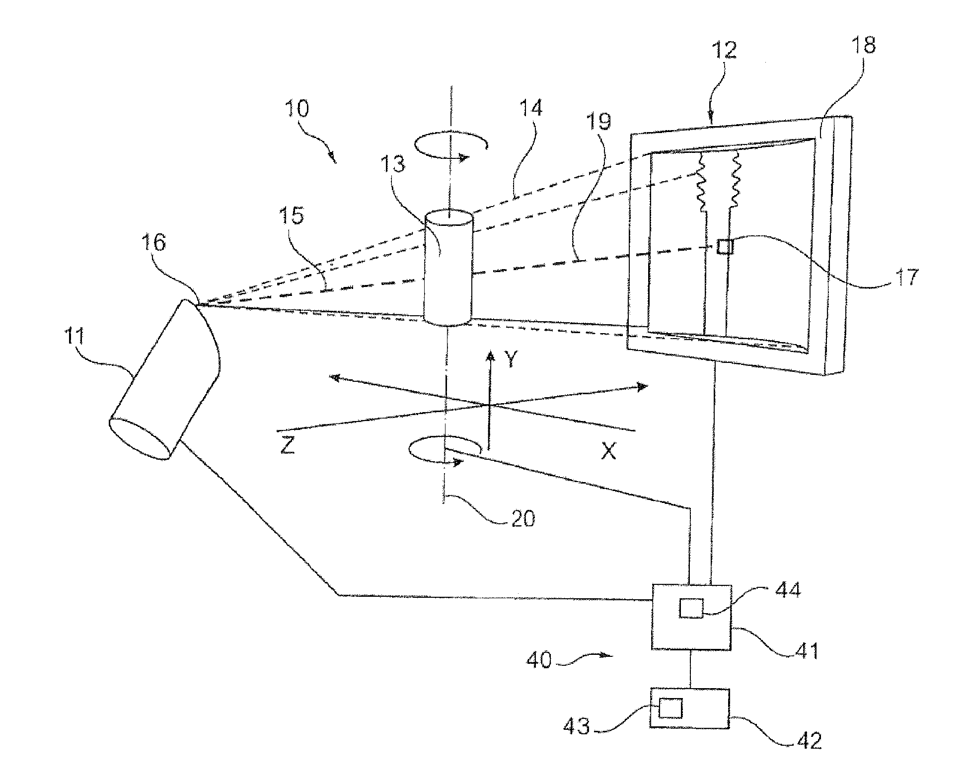
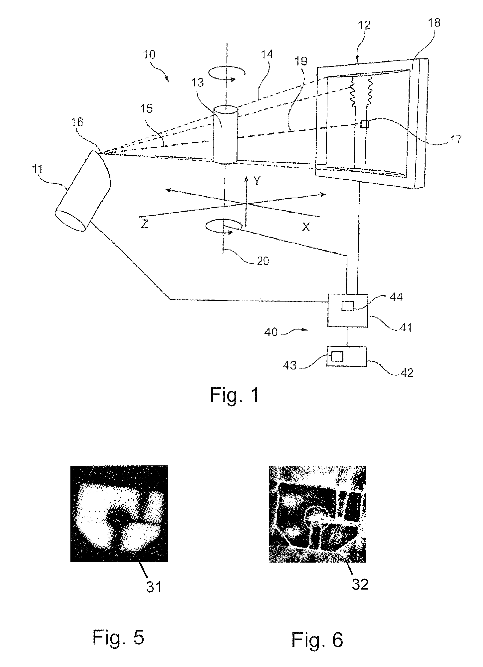
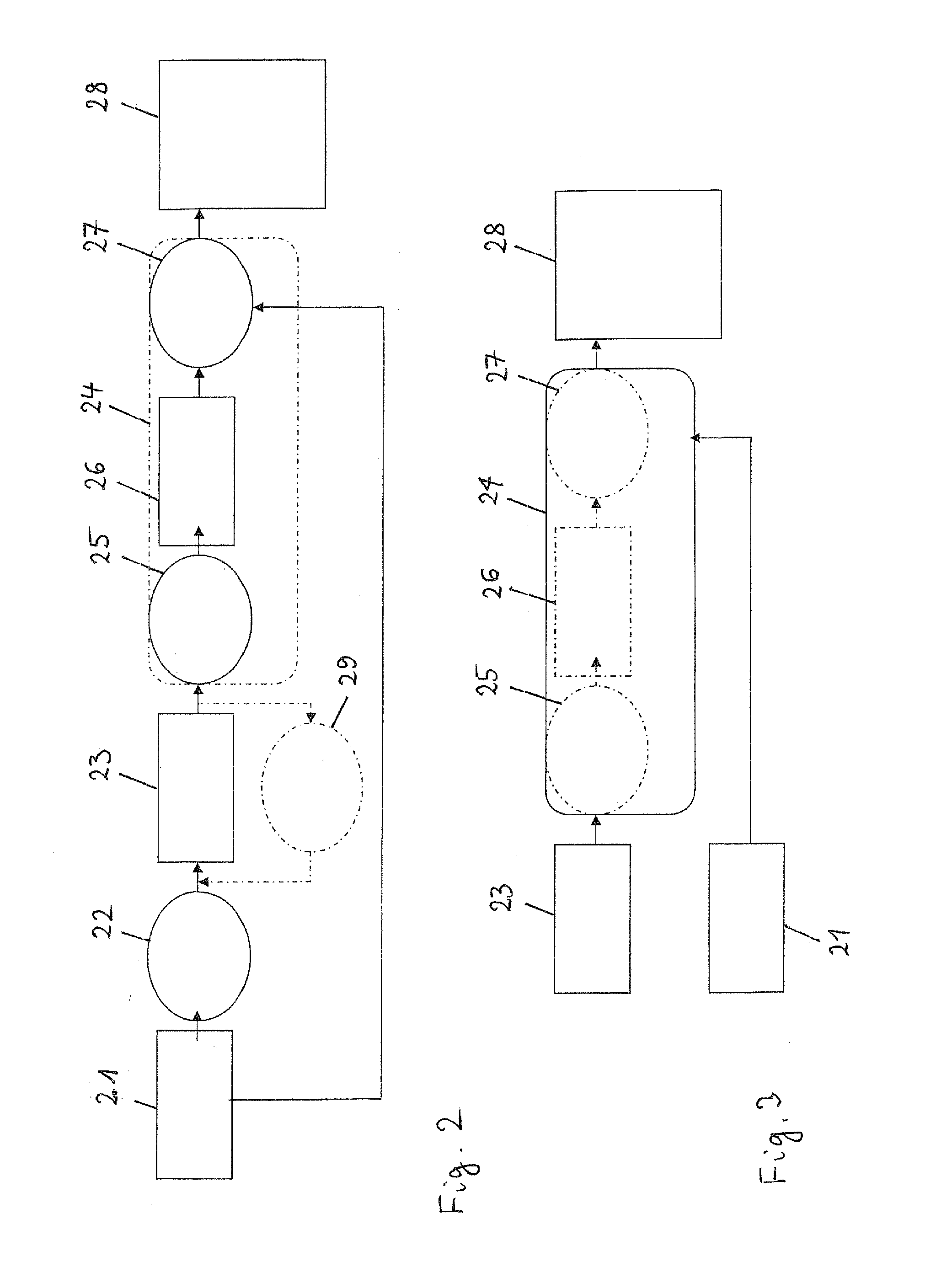
[0031]In a first embodiment shown in FIG. 3, a forward projection 25 is applied to the reconstructed volume slices 23 for generating artificial projections 26 of the sample 13. The forward projection 25 is a mathematical method which simulates the x-ray system 10 shown in FIG. 1 using geometric projection models of a scanner, taking into account the geometry of the x-ray system 10 shown in FIG. 1 in order to make the artificial projections 26 comparable to the x-ray projections 21 recorded with the x-ray system 10. The artificial projections 26 are one- or two-dimensional artificially computed images each having a plurality of pixels.

[0032]Based on a comparison between the artificial projections 26 and the x-ray projections 21 recorded with the x-ray system 10, individual confidence measures, or quality measures, for each voxel of the reconstructed volume data 23 are then calculated in a confidence measure calculating step 27.

[0033]In more detail, the confidence measure of a voxel m...

second embodiment

[0035]In a second embodiment shown in FIG. 4 the reconstructed volume data 23 can be individually changed or manipulated in a predetermined manner in a voxel changing step 29 prior to the further processing of the reconstructed volume data. For example, every single voxel of the sample volume can be set to a predetermined specific value in the voxel changing step 29 to generate changed volume data 30, in particular in the form of changed volume slices. In another example every single voxel can be replaced by a set of some predetermined densities.

[0036]The forward projection 25 is then applied to the changed volume data 30 for generating artificial projections 26 of the sample 13. To compute confidence measures for voxel elements of a given volume it may be necessary to repeat this step 24 iteratively. The confidence measure calculating step 27 may in this embodiment comprise an intermediate step of calculating a confidence value distribution, i.e. a plurality of confidence values, f...


PUM


Abstract

A computed tomography method for determining a volumetric representation of a sample comprises using reconstructed volume data of the sample from x-ray projections of the sample taken by an x-ray system, computing a set of artificial projections of said sample by a forward projection from said reconstructed volume data , and determining, essentially from process data of said reconstruction including said reconstructed volume data and / or said x-ray projections, individual confidence measures for single voxels of said volume data based on calculating, for each of said measured x-ray projections, the difference between the contribution of this measured x-ray projection to the voxel under inspection and the contribution from a corresponding artificial projection to the voxel under inspection.

Description

CROSS-REFERENCE TO RELATED APPLICATION(S)[0001]The subject application claims priority under 35 U.S.C. §119(e) of European Patent Application No. 09 014 798.4, filed on Nov. 27, 2009, which is hereby incorporated by reference in its entirety, including any figures, tables, or drawings.BACKGROUND OF THE INVENTION[0002]The invention relates to a computed tomography method according to the preamble of claim 1, a computer software, a computing device and computed tomography system.[0003]In computed tomography it is a common problem that the inability to distinguish artifacts from real irregularities and structures in the reconstructed volume data can cause misinterpretation of the reconstructed volume data. This can lead for example to detection problems with automated analysis algorithms applied to the reconstructed volume data. The above problem can generally be addressed by determining the quality of the volume data, which is usually done by comparing the reconstructed volume data to...

Claims


Application Information

Patent Timeline
IPC IPC(8): A61B6/03G06K9/00
CPCG06T2211/424G06T11/006
Inventor NEUSER, EBERHARDSUPPES, ALEXANDERROTHE, NILSHOETTER, MICHAELFROST, ANJA
Owner GE SENSING & INSPECTION TECH GMBH
Learn More