Optical scanning apparatus and image forming apparatus

an image forming apparatus and optical scanning technology, applied in the direction of optics, electrographic process apparatus, instruments, etc., can solve the problems of high degree of warping, increased localized thermal deformation, and heat generation of polygon motors when driven, and achieve uniform pitch

Inactive Publication Date: 2011-06-02
KYOCERA DOCUMENT SOLUTIONS INC
View PDF10 Cites 9 Cited by
  • Summary
  • Abstract
  • Description
  • Claims
  • Application Information

AI Technical Summary

Benefits of technology

[0014]The present invention, conceived to address the above-mentioned problem, is designed to enable reduction in size of an optical scanning apparatus and to suppress failure of light guiding of optical beams resulting from thermal deformation in a housing.
[0016]According to this aspect of the present invention, the housing includes the base portion enabling installation of the optical beam emission unit, the light guiding unit and the deflection unit, and a cover portion including the indented heat emission channel that transmits the heat in the housing to the fluid. Therefore thermal deformation in the housing resulting from the heat emission channel is concentrated in the cover portion and the effect on the base portion which installs the optical beam emission unit, the light guiding unit and the deflection unit can be reduced. Therefore according to this aspect of the present invention, light-guiding failure of the optical beams in the optical scanning apparatus caused by thermal deformation of the housing can be suppressed.
[0017]According to this aspect of the present invention, since the optical beams deflected by the deflection device are returned by the reflective mirror and travel along the upper surface and the lower surface of the base plate of the housing, the width of the housing with reference to a direction of height can be effectively suppressed and therefore enables downsizing of the housing.
[0019]According to this aspect of the present invention, since two optical scanning apparatuses that can optically scan two photosensitive members at the same time are disposed in parallel on a color image forming apparatus, a total of four photosensitive members can be optically scanned by optical beams corresponding to four-color (magenta, cyan, yellow and black) image information. However since a first opening is formed between the imaging lens and the first reflective mirror on an optical path connecting the third reflective mirror and the photosensitive member on the base plate formed on the housing of each optical scanning apparatus, a substantially uniform pitch is enabled between the four photosensitive members.

Problems solved by technology

However the polygon motor mounted on the control board produces heat when driven.
When a draft air duct is formed randomly as an indentation with respect to the above type of housing, there is a risk that localized thermal deformation may increase as a result of large change in the shape of the housing from a square shape, and that the installation region for the optical beam generating device, the polygon mirror, the optical components, and the like will be subjected to a high degree of warping.
When warping occurs in the installation region for the optical beam generating device, the polygon mirror, the optical components, and the like in the housing, those components become inclined and light beams can no longer be suitably guided.
Consequently, problems arise in relation to the increased size of the housing.
Alternatively, a large width must be ensured in a height direction of the imaging lens provided for constant-speed scanning of the two light beams, and this causes cost increases.
Alternatively, in the above optical scanning apparatus, since the optical path only returns once from the deflection device to the photosensitive member, there is the problem that there is an increase in the width in the height direction of the housing.
Consequently, the thermal deformation amount of the housing due to temperature fluctuation increases, the scanning position of optical beams deviates and therefore tends to result in problems in relation to color shift.

Method used


Image

  • Optical scanning apparatus and image forming apparatus
  • Optical scanning apparatus and image forming apparatus
  • Optical scanning apparatus and image forming apparatus

Examples


Embodiment Construction

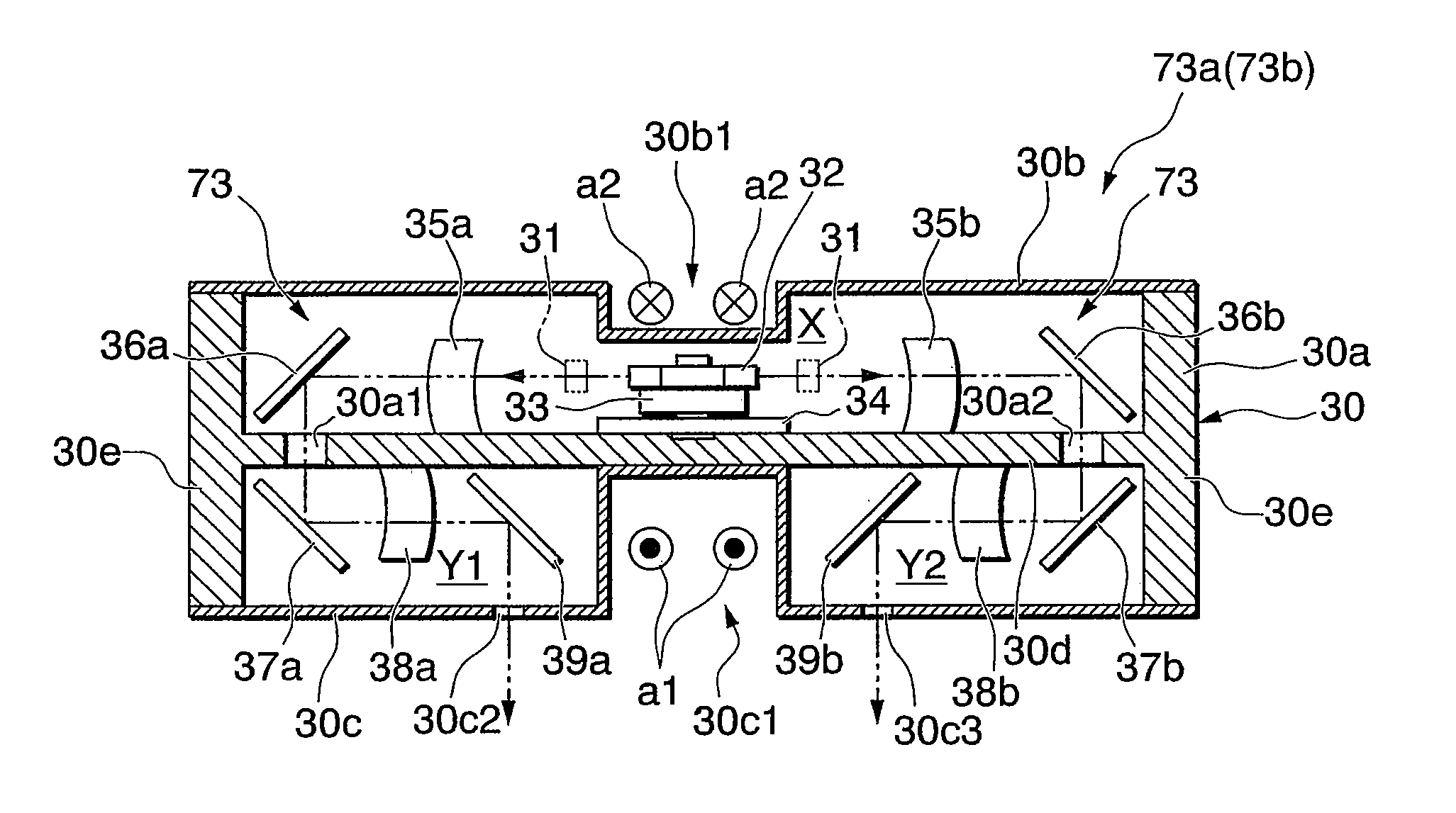
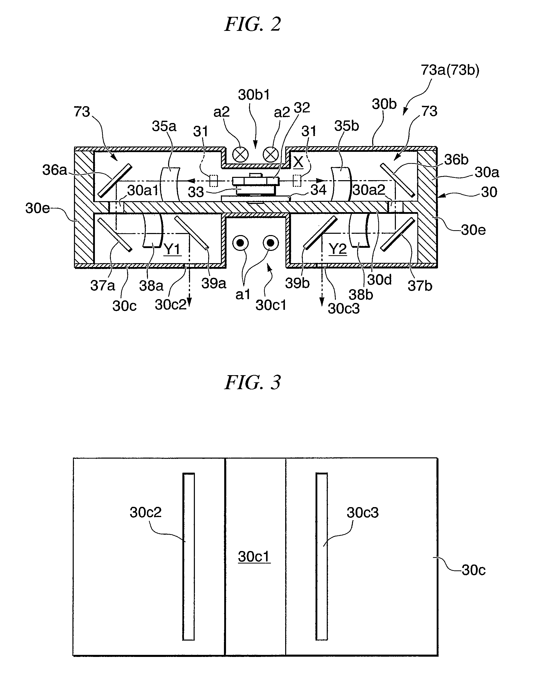
[0029]The embodiments of an optical scanning apparatus and an image forming apparatus will be described below referring to the figures. In the figures below, the dimensions of each member has been suitably varied to thereby show each member in a size that enables recognition. In the following description, an example of an image forming apparatus according to the present invention will be described with reference to a copying machine.

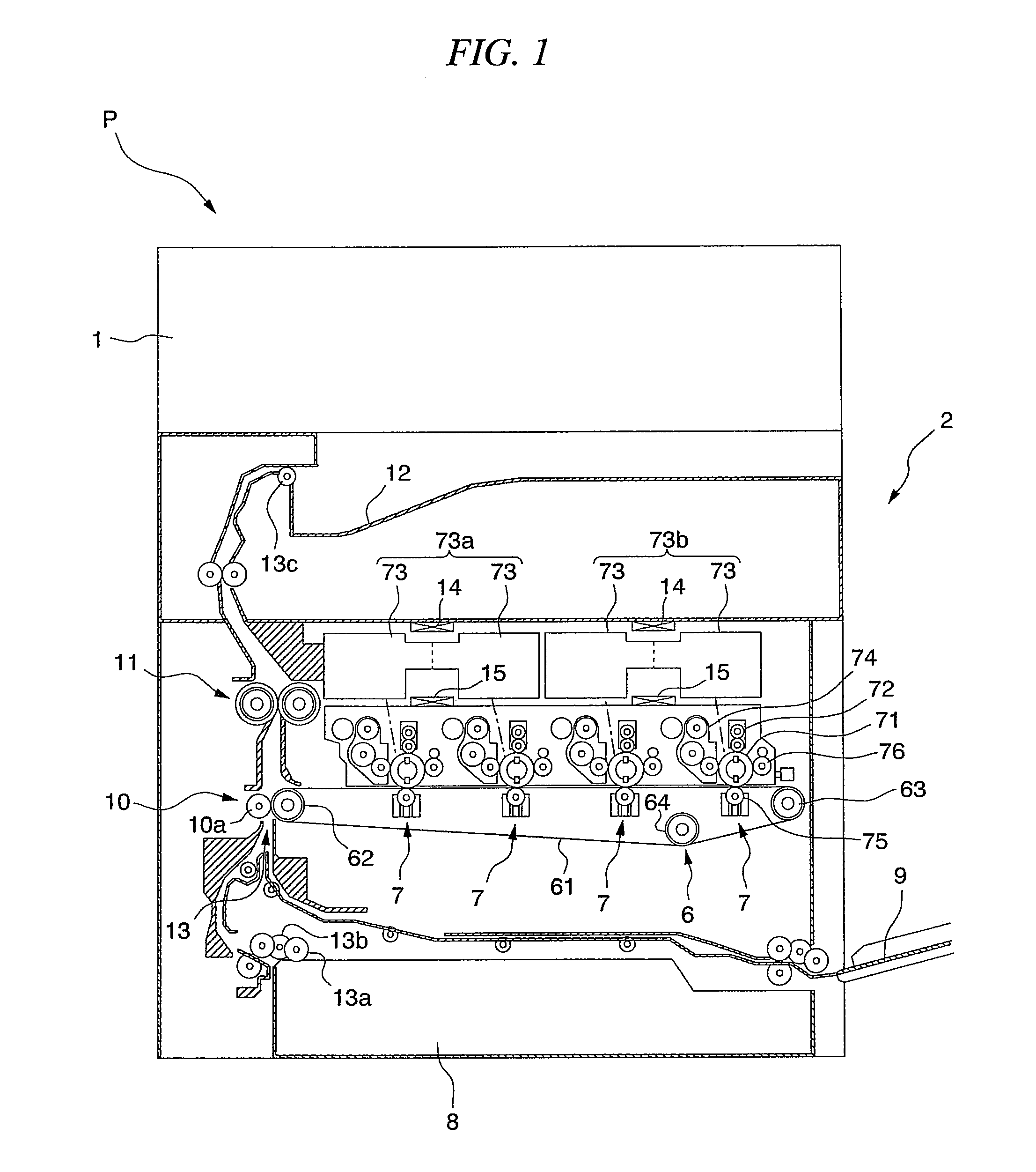
[0030]FIG. 1 is a sectional view showing a schematic configuration of a copying machine P according to the present embodiment. As shown in the figure, the copying machine P according to the present embodiment includes an image reading unit 1 for reading an image of a document and a printing unit 2 that performs printing onto a recording sheet (recording medium) based on the read image data.

[0031]The image reading unit 1 illuminates light onto the image of the document to thereby read the image of the document as image data by receiving the reflected ligh...


PUM


Abstract

A housing (30) includes a base portion (30a) for installation of an optical beam emission unit (31), a light guiding unit (35a-39a, 35b-39b), and a deflection unit (32, 33), and a cover portion (30b, 30c) that includes an indented heat emission channel (30b1, 30c1) that transmits heat in an inner portion of the housing (30) to a fluid.

Description

CROSS-REFERENCE TO RELATED APPLICATION[0001]This application is a non-provisional application claiming priority to and the benefit of Japanese Patent Application No. 2009-297259, filed Dec. 28, 2009, Japanese Patent Application No. 2009-271156, filed Nov. 30, 2009. The entire contents of which are incorporated herein by reference.BACKGROUND OF THE INVENTION[0002]1. Field of the Invention[0003]The present invention relates to an optical scanning apparatus and an image forming apparatus.[0004]2. Description of the Related Art[0005]In an image forming apparatus such as a copying machine, a printer, a multifunction peripheral, or the like, a photosensitive member has a surface that is uniformly charged by a charging device and is optically scanned by an optical scanning apparatus to thereby form an electrostatic latent image on its surface in response to image information. Thereafter the electrostatic latent image is developed by a developing device using toner as a developing agent and...

Claims


Application Information

Patent Timeline
Patent Type & Authority Applications(United States)
IPC IPC(8): G03G15/04G02B26/10
CPCH04N1/00519H04N1/00986H04N1/113G02B26/125G02B26/103G03G21/20G03G2215/0404G03G15/0435G03G15/04045G03G15/326
Inventor NAKANO, ISSEIFUKUMA, NOBUHIRONAKAI, JUN
Owner KYOCERA DOCUMENT SOLUTIONS INC
Why Eureka
Try Eureka