Method, apparatus and system for reducing vibration in a rotary system of an aircraft, such as a rotor of a helicopter

a rotary system and aircraft technology, applied in the direction of propellers, propulsive elements, water-acting propulsive elements, etc., can solve the problems of material fatigue, material fatigue, and affecting safety and comfort, so as to improve the effect of balancing

Inactive Publication Date: 2011-06-02
PROF DR LARS BERTIL CARNEHAMMAR
View PDF8 Cites 22 Cited by
  • Summary
  • Abstract
  • Description
  • Claims
  • Application Information

AI Technical Summary

Benefits of technology

[0048]Another aspect of the invention is a method, wherein a weight body is in contact with said thixotropic balancing substance 338a; 338b; 438a; 438b; 438c; 538a; 538b; 538c. As a consequence, the weight body may contribute to balancing of the rotary system 140; 240a; 240b; 340a; 340b, and as a result, the effect of the balancing may be improved, and the amount of said thixotropic balancing substance 338a; 338b; 438a; 438b; 438c; 538a; 538b; 538c may be reduced.
[0049]Another aspect of the invention is a method, wherein said weight body has, defined by a body size of said weight body, a body surface and a body weight, such that said weight body overcomes adhesion between said body surface and said thixotropic balancing substance 338a; 338b; 438a; 438b; 438c; 538a; 538b; 538c when said thixotropic balancing substance 338a; 338b; 438a; 438b; 438c; 538a; 538b; 538c is subjected to said vibration and changes in an agitated state. As a consequence, the body size ensures movability of the weight body in the chamber 232a, 233a, 234b, 235a, 236a, 237a; 232b, 233b, 234b, 235b, 237b; 335a; 335b; 433a; 433b; 433c; 535a; 535b; 535c with the thixotropic balancing substance 338a; 338b; 438a; 438b; 438c; 538a; 538b; 538c therein, and as a result, the effect of the balancing may be improved.
[0050]Another aspect of the invention is a method, wherein said weight body preferably is a ball. The body size corresponds with a diameter of the ball. The diameter may be determined by a ratio between the body surface according to A=4 pi r̂2 accounting for surface structure, i.e. roughness, and adhesion, and a body volume according to V=4 / 3 pi r̂3 accounting for body density and body weight. For increasing radius r, the body volume, and therefore body, weight increases faster than the body surface. As a consequence, movability of the weight body in the chamber 232a, 233a, 234b, 235a, 236a, 237a; 232b, 233b, 234b, 235b, 237b; 335a; 335b; 433a; 433b; 433c; 535a; 535b; 535c may be increased, and as a result, the effect of the balancing may be improved.
[0051]Another aspect of the invention is a method, wherein said weight body comprises metal, for example steel, such as stainless steel. As a consequence, durability of the weight body in the chamber 490; 590; 690; 790; 890a-c; 990; 1090; 1190; 1250, 1260, 1290; 1390 may be improved, and as a result, maintenance work may be simplified and reduced.

Problems solved by technology

Vibration negatively effects safety and comfort.
With regard to safety, vibration has a direct influence on stability and may cause material fatigue.
The blades change over time, and they tend to get heavier in service.
There is blade wear or erosion owing to hard particles, such as sand.
Furthermore, owing to light-weight construction of the blades, air cells in the blades may fill with water, in particular where a skin of the blades becomes porous.
This is known as water-ingress or trapped-water problem.
As a consequence, vibration in the rotor system increases.
The RTB is time-consuming and costly.

Method used


Image

  • Method, apparatus and system for reducing vibration in a rotary system of an aircraft, such as a rotor of a helicopter
  • Method, apparatus and system for reducing vibration in a rotary system of an aircraft, such as a rotor of a helicopter
  • Method, apparatus and system for reducing vibration in a rotary system of an aircraft, such as a rotor of a helicopter

Examples


Embodiment Construction

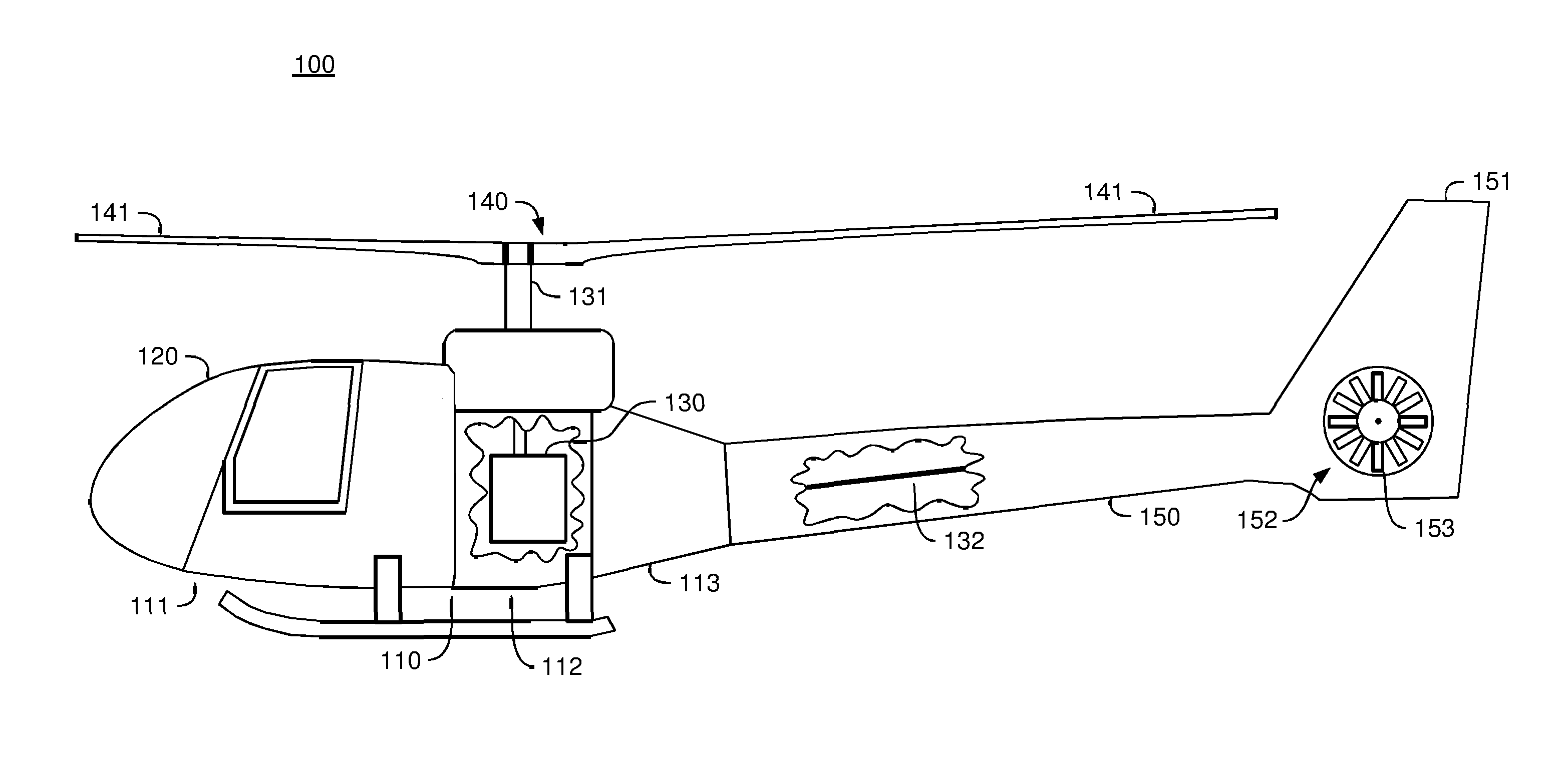
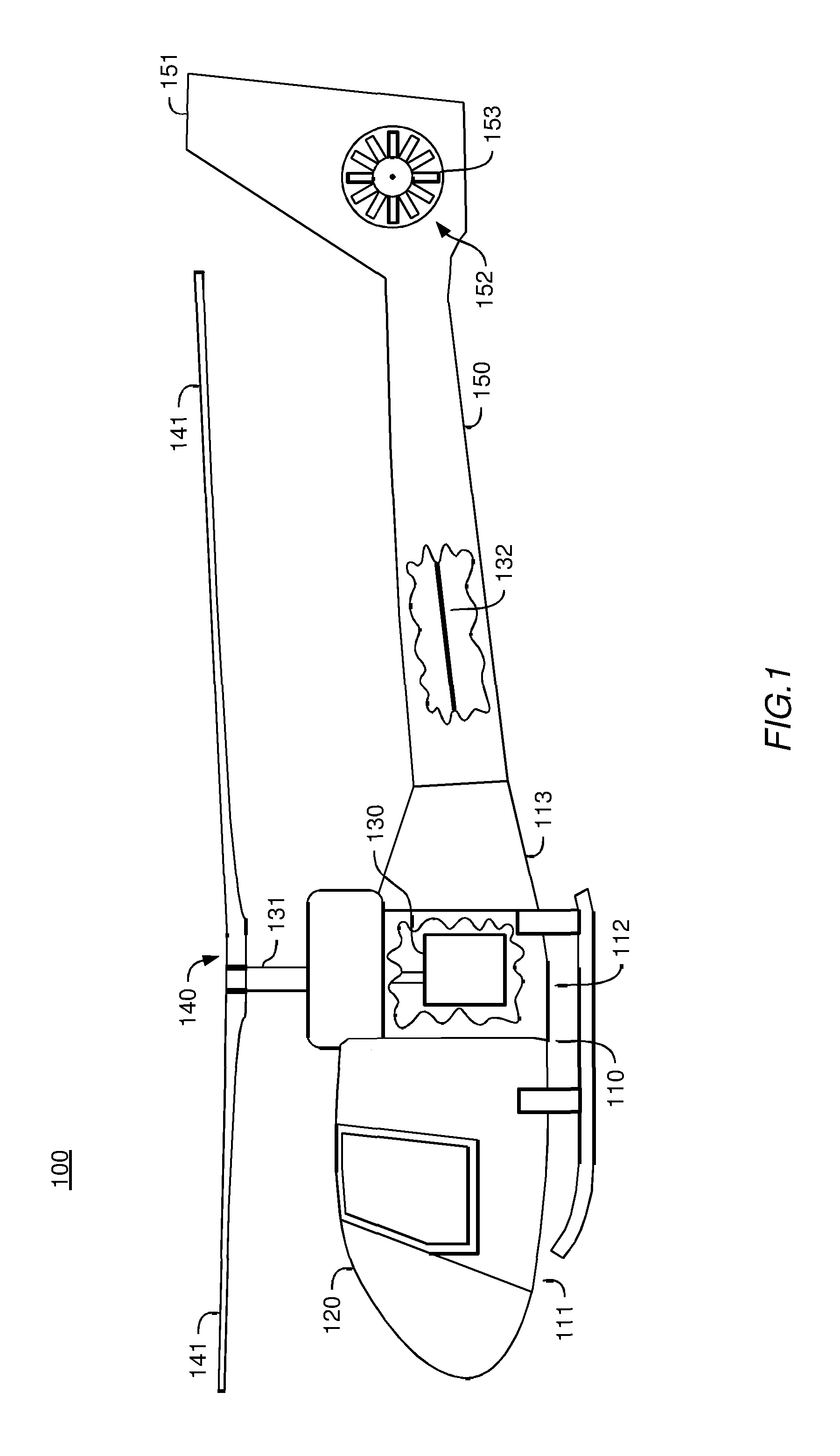
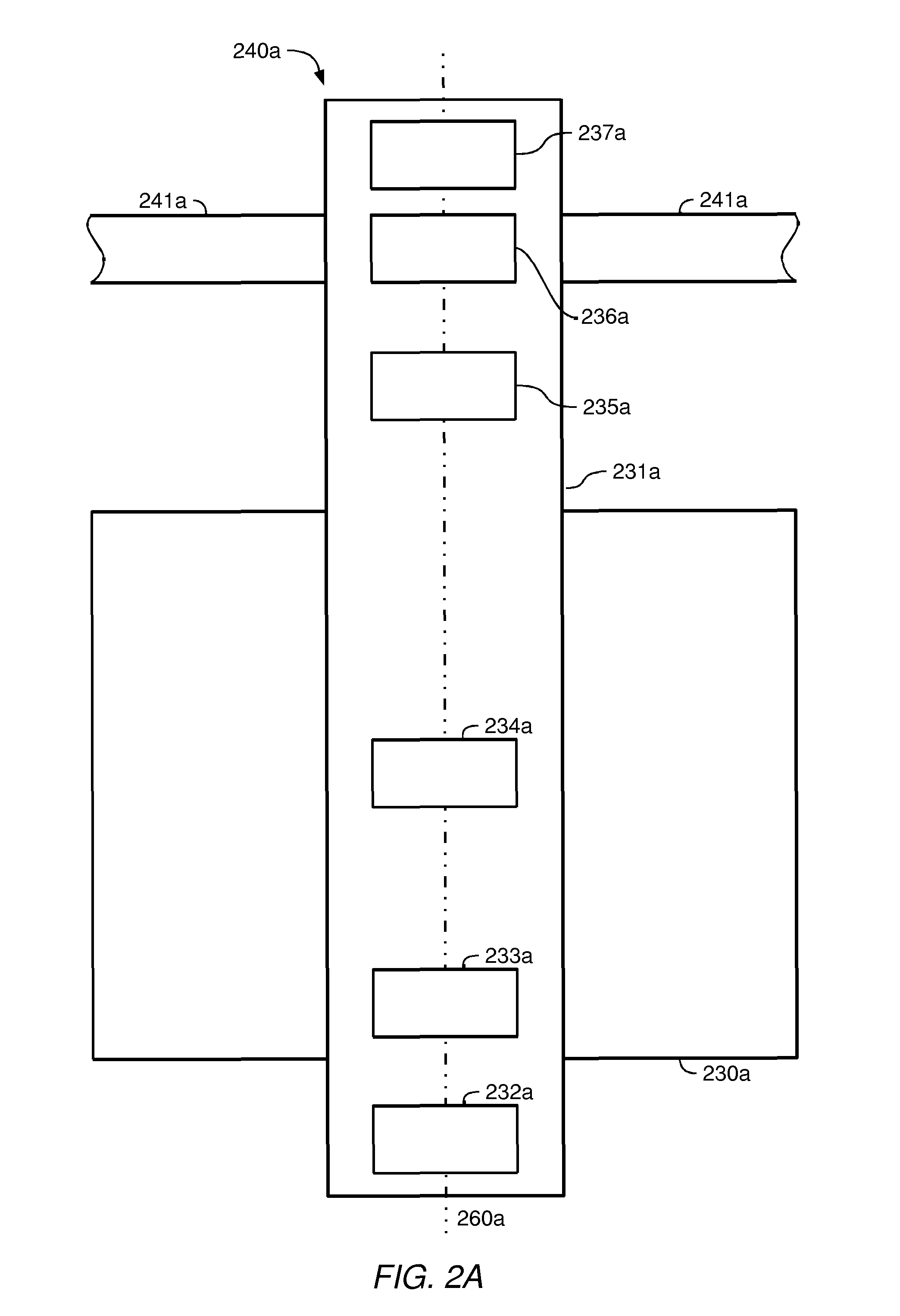
[0062]In the following detailed description of the embodiments, reference is made to the accompanying drawings which form a part hereof and show, by way of illustration, specific embodiments in which the invention may be practiced. In the drawings, like numerals describe substantially similar components throughout the several views. The embodiments are intended to describe aspects of the invention in sufficient detail to enable those of skill in the art to practice the invention. Other embodiments may be utilized and structural, logical or electrical changes or combinations thereof may be made without departing from the scope of the invention. Moreover, it is to be understood, that the various embodiments of the invention, although different, are not necessarily mutually exclusive. For example, a particular feature, structure or characteristic described in one embodiment may be included within other embodiments. Furthermore, it is to be understood, that embodiments of the invention ...


PUM


Abstract

A method for reducing vibration in a rotary system (140; 240a; 240b; 340a; 340b) of an aircraft (100), for example an aeroplane or a rotorcraft, such as a helicopter, comprising balancing said rotary system (140; 240a; 240b; 340a; 340b), characterized by providing a substantially circular chamber (232a, 233a, 234b, 235a, 236a, 237a; 232b, 233b, 234b, 235b, 237b; 335a; 335b; 433a; 433b; 433c; 535a; 535b; 535c) having a fulcrumon an axis (260a; 260b; 360a; 360b; 460a; 460b; 460c; 560a; 560b; 560c) of a shaft (131; 231a; 231b; 331a; 331b; 431a; 431b; 431c; 531a; 531b; 531c) of said rotary system (140; 240a; 240b; 340a; 340b) and being partially filled with an amount of a thixotropic balancing substance (338a; 338b; 438a; 438b; 438c; 538a; 538b; 538c). An apparatus, and a system, for reducing vibration in a rotary system (140; 240a; 240b; 340a; 340b) of an aircraft (100) according to the method.

Description

FIELD OF THE INVENTION[0001]Embodiments of the invention described herein relate generally to reducing vibration, and more particularly to a method, an apparatus and a system for reducing vibration in a rotary system of an aircraft, such as a rotor of a helicopter.BACKGROUND OF THE INVENTION[0002]Vibration is a major environmental factor in aircraft operations. Vibration negatively effects safety and comfort. With regard to safety, vibration has a direct influence on stability and may cause material fatigue. A main source of vibration is a rotary system of the aircraft, for example an engine system of the aircraft, such as a rotor system of a helicopter.[0003]Rotor blades (“blades”) of the helicopter's rotor system may comprise, for example, wood or composite materials, such as glass-fibre-reinforced material or carbon-fibre-reinforced material. The blades change over time, and they tend to get heavier in service. There is blade wear or erosion owing to hard particles, such as sand....

Claims


Application Information

Patent Timeline
Patent Type & Authority Applications(United States)
IPC IPC(8): B64C27/00B64C27/473
CPCF16F15/366B64C27/001B64C27/32B64C27/51F16F15/36
Inventor SEITZ, NORBERT
Owner PROF DR LARS BERTIL CARNEHAMMAR
Why Eureka
Try Eureka