
Ballistic Resistant Composite Fabric

a composite fabric and ballistic resistance technology, applied in the field of fluoropolymer composite fabrics, can solve the problems of reducing the life of the rope, lcp fibers are particularly susceptible to this failure mechanism, and the tensile and bending stresses of high-tensile and bending stress, and achieve the effect of improving the handleability of the ballistic resistance fabri

Inactive Publication Date: 2011-06-02
WL GORE & ASSOC INC
View PDF38 Cites 36 Cited by
  • Summary
  • Abstract
  • Description
  • Claims
  • Application Information

AI Technical Summary

Benefits of technology

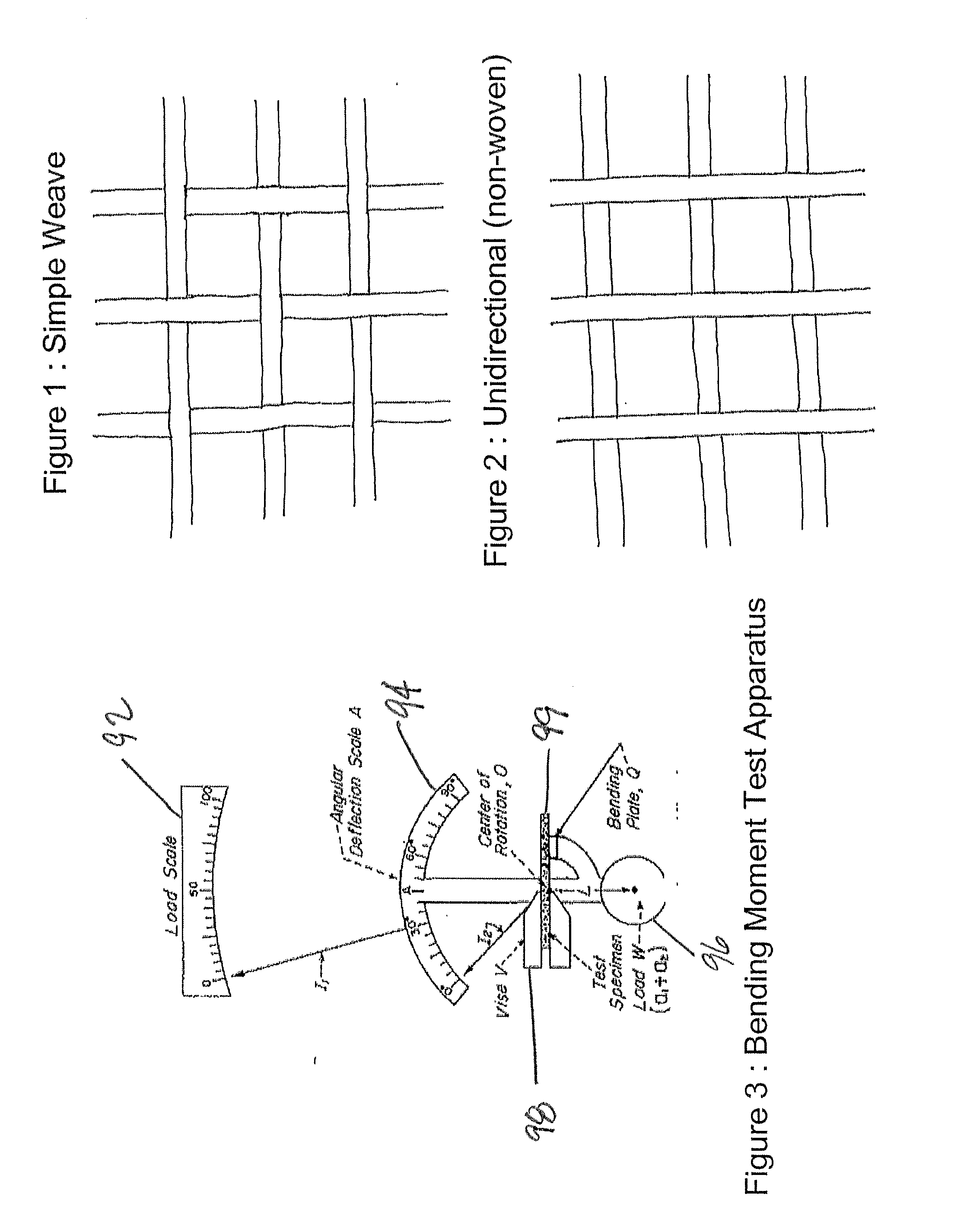
[0019]In another aspect, the invention provides a method of improving the handleability of a ballistic resistant fabric comprising the step of incorporating into the fabric at least one fiber of expanded PTFE to produce a bending moment of the fabric of less than 0.0008 N-m.

Problems solved by technology

They are subjected to high tensile and bending stresses in use as well as a wide range of environmental challenges.
The abrasion damages the fibers, thereby decreasing the life of the rope.
LCP fibers are particularly susceptible to this failure mechanism.
This internal heat severely weakens the fibers.
The UHMWPE fibers suffer from this mode of failure.
All such ropes, however, still perform inadequately in some applications, failing due to one or more of the three above-mentioned mechanisms.
For example, UHMWPE fibers and high strength fibers, such as LCP fibers, have been blended to create a large diameter rope with better abrasion resistance, but they are still not as effective as desired.
Typically such coatings wear off relatively quickly.
Jackets add weight, bulk, and stiffness to the rope, however.
Although the fabrics made from these high strength fibers alone have suitable ballistic resistance, they are stiff and therefore uncomfortable to wear.
These fabrics also suffer from low breathability.
A ballistic resistant fabric with decreased stiffness and / or improved breathability is very desirable, and yet no satisfactory such fabric has yet been developed.
In sum, none of the known attempts to improve the life of ropes or cables have provided sufficient durability in applications involving both bending and high tension.
Nor has a suitably comfortable ballistic resistant fabric heretofore been available.
Furthermore, no suitably comfortable and durable ballistic resistant fabric heretofore has been available.

Method used


Image

  • Ballistic Resistant Composite Fabric
  • Ballistic Resistant Composite Fabric
  • Ballistic Resistant Composite Fabric

Examples


examples

[0036]In the examples presented below, various samples and comparative samples were prepared and tested according to the described test methods. The examples are intended to illustrate the invention, but not to limit it. Rather, the inventors intend for their invention to be given the full scope of the appended claims.

Testing Methods

V50 Test

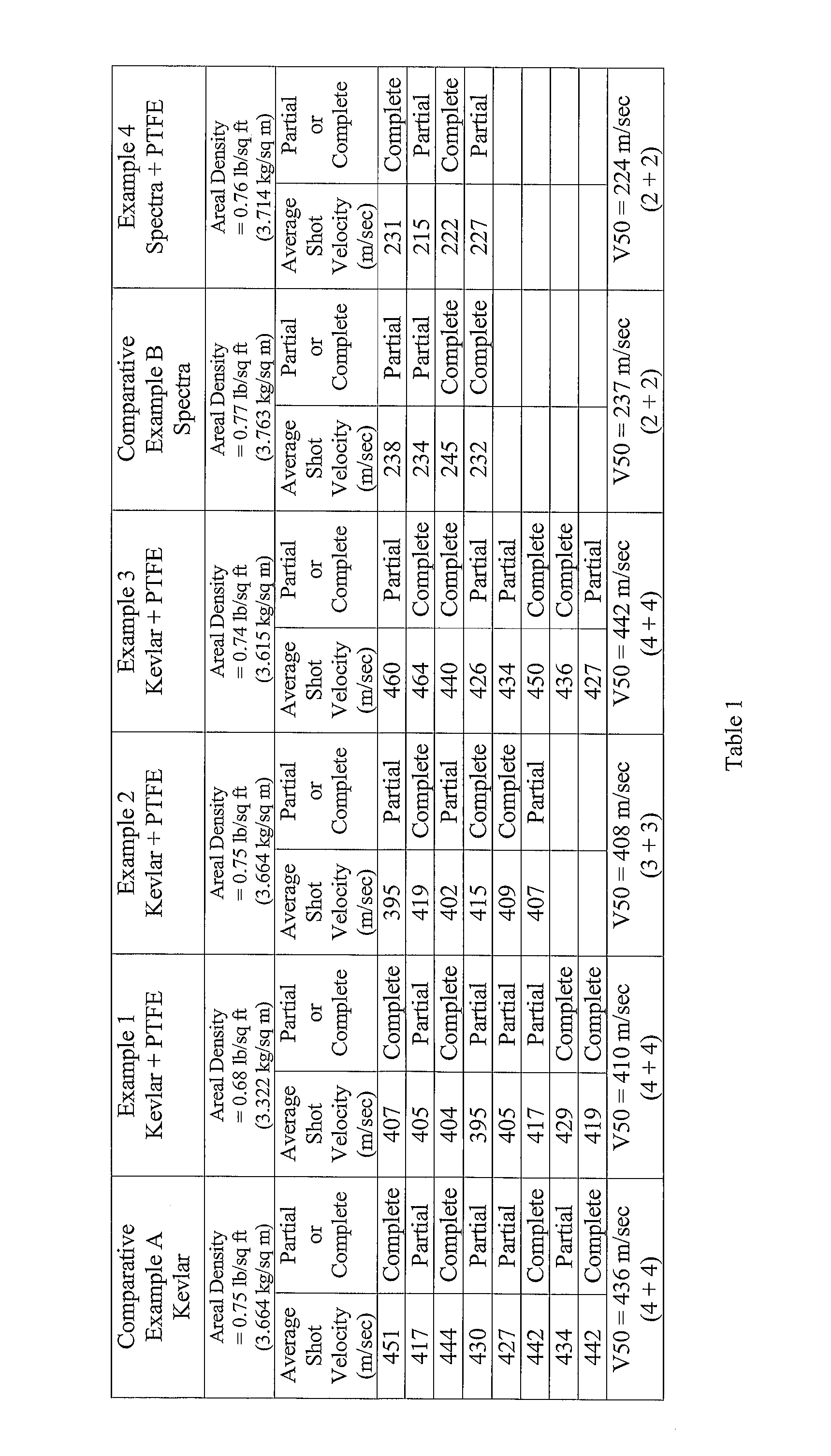
[0037]A 15 inch (38.1 cm) by 18 inch (45.7 cm) panel was constructed using multiple plies of the woven fabric material to achieve an areal density (i.e., mass per unit area) for the panel of about 0.75 lb / sq ft (3.7 kg / sq m). Each panel had a 1 inch (2.54 cm) perimeter stitch and an x-stitch through the diagonals of the panel served to hold the layers together. Panels were tested to measure V50, the velocity of a bullet corresponding to the 50% probability that a bullet will completely pass through the panel. The tests were performed as follows. Each panel was placed inside a 70d black nylon pouch. The pouch was then fixed to a backing material c...

example 1

Kevlar Plus ePTFE

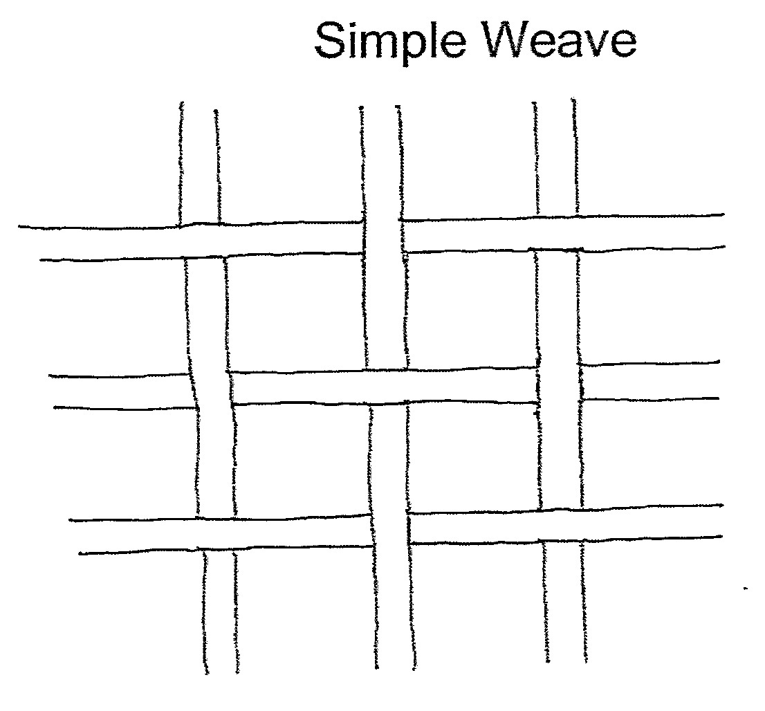
[0048]A non-twisted 600d Kevlar fiber (Part Number X300 1F1618, E.I. DuPont de Nemours, Inc., Wilmington, Del.) and 400d multifilament ePTFE fiber (Part Number V112939, W.L. Gore & Associates, Inc., Elkton, Md.) were obtained. The ePTFE fiber was twisted at 4 twists / inch (157 twists / m) in a Z configuration. A simple weave having 29 pics / inch (11.4 pics / cm) and 29 ends / inch (11.4 ends / cm) was created using one ePTFE fiber for every 3 Kevlar fibers. The resulting weave, therefore, consisted of about 18% PTFE by weight.

[0049]A 15 inch (38.1 cm) by 18 inch (45.7 cm) panel was then constructed using 23 plies of the simple weave material in the following manner. A 1 in (2.54 cm) perimeter stitch and an x-stitch through the diagonals of the panel served to hold the layers together. The choice of 23 plies was based on achieving a value of areal density (i.e., the mass per unit area) of the panel of close to 0.75 lb / sq ft (3.664 kg / sq meter). The actual value was 0.68 lb / sq ...

example 2

Kevlar Plus ePTFE

[0052]A non-twisted 600d Kevlar fiber (Part Number X300 1F1618, E.I. DuPont de Nemours, Inc., Wilmington, Del.) and 500d monofilament ePTFE fiber (Part Number 10328808, W.L. Gore & Associates, Inc., Elkton, Md.) were obtained. A simple weave having 29 pics / inch (11.4 pics / cm) and 29 ends / inch (11.4 ends / cm) was created using one ePTFE fiber for every 3 Kevlar fibers. The resulting weave, therefore, consisted of about 22% PTFE by weight.

[0053]A 15 inch (38.1 cm) by 18 inch (45.7 cm) panel was then constructed using 23 plies of the simple weave material in the following manner. A 1 in (2.54 cm) perimeter stitch and an x-stitch through the diagonals of the panel served to hold the layers together. The areal density (i.e., the mass per unit area) of the panel was 0.75 lb / sq ft (3.664 kg / sq meter).

[0054]The V50 test results follow. The panel was shot a total of 9 times with a minimum shot spacing of 3 inch (7.6 cm). The average bullet velocity ranged from 1286 ft / sec (39...


PUM

PropertyMeasurementUnit
perimeteraaaaaaaaaa
humidityaaaaaaaaaa
temperatureaaaaaaaaaa

Abstract

A ballistic resistant article comprising high strength Kevlar fibers and expanded PTFE fibers, wherein the article is a fabric further comprising a V50 of greater than about 1420 ft / s (433 m / s) at a fabric weight of about 0.75 lb / ft2 (3.7 kg / sq m) and a bending moment at room temperature of less than about 0.0008 N-m. A ballistic resistant article comprising high strength Spectra fibers and expanded PTFE fibers, wherein the article is a fabric further comprising a V50 of greater than about 735 ft / s (224 m / s) at a fabric weight of about 0.75 lb / ft2 (3.7 kg / sq m) and a bending moment at room temperature of less than about 0.0007 N-m.

Description

RELATED APPLICATIONS[0001]This application is a continuation-in-part of pending U.S. patent application Ser. No. 11 / 557,319 filed Nov. 7, 2006, which is in turn a divisional application of U.S. patent application Ser. No. 11 / 056,074 filed Feb. 11, 2005, abandoned.FIELD OF THE INVENTION[0002]The present invention relates to a fluoropolymer composite fabric and, more particularly, to ballistic resistant composite fabric including high strength fibers and fluoropolymer fibers such as expanded polytetrafluoroethylene (PTFE).DEFINITION OF TERMS[0003]As used in this application, the term “fiber” means a continuous (as opposed to staple) threadlike article, including monofilament and multifilament constructions. “High strength fiber” as used herein means a fiber having a tenacity of greater than 15 g / d. “Ballistic resistance fabric” as used herein means a fabric having a V50 of greater than about 1420 ft / s (433 m / s), according to testing procedures described herein below. “Room temperature...

Claims


Application Information

Patent Timeline
Patent Type & Authority Applications(United States)
IPC IPC(8): B32B5/02
CPCB32B5/024B32B5/06F41H5/0485D10B2331/021D10B2321/042D10B2321/0211D07B2205/2096D07B2205/2071D07B2205/205B32B5/26B32B2250/20B32B2262/0253B32B2262/0269B32B2571/02D02G3/047D02G3/442D07B1/025D07B2201/2014D07B2201/2036D07B2201/2041D07B2205/2014D07B2801/10Y10T428/249921
Inventor CLOUGH, NORMAN
Owner WL GORE & ASSOC INC
Learn More