System And Method Using Coupler-Resonators For Electron Paramagnetic Resonance Spectroscopy

a coupler resonance and electron paramagnetic resonance technology, applied in the field of electron paramagnetic resonance, can solve the problems of not always easy to ensure that biopsy samples are actually taken from tissue, not always easy to ensure that biopsy samples are taken from tissue, and not always easy to ensure that recalled history alone is not always a good indicator of exposure to toxic or radioactive materials and the corresponding need for treatmen

Inactive Publication Date: 2011-06-02
THE TRUSTEES OF DARTMOUTH COLLEGE NONEPROFIT CORP
View PDF14 Cites 9 Cited by
  • Summary
  • Abstract
  • Description
  • Claims
  • Application Information

AI Technical Summary

Problems solved by technology

The device of FIG. 1 was tested implanted in an animal, but was not used on teeth or fingernails, and proved too stiff for use in measurements in highly mobile organs such as heart.
It is known that it is not always easy to ensure that biopsy samples are actually taken from a tissue of interest, such as a tumor.
In large scale disasters, recalled history alone has proven to not always be a good indicator of exposure to toxic or radioactive materials and corresponding need for treatment.
Similarly, apparent physical injuries and symptoms are not good indicators of intensity of radiation doses received by a subject.
When a radiation disaster, whether by accident like Chernobyl, or weapon like Hiroshima, happens, medical care systems will likely be overloaded.
In such an event, an area of heart muscle that has been deprived of blood flow may be substantially damaged, or may die and be replaced by scar tissue, resulting in permanent impairment of heart function.
While both treatment methodologies often restore blood flow to the area of muscle that was deprived of blood flow before the muscle tissue dies, it has been found that some permanent damage often remains.
It is known that some of this permanent damage results from oxidative damage after blood flow is restored—this is known a reperfusion injury.

Method used


Image

  • System And Method Using Coupler-Resonators For Electron Paramagnetic Resonance Spectroscopy
  • System And Method Using Coupler-Resonators For Electron Paramagnetic Resonance Spectroscopy
  • System And Method Using Coupler-Resonators For Electron Paramagnetic Resonance Spectroscopy

Examples


embodiment 200

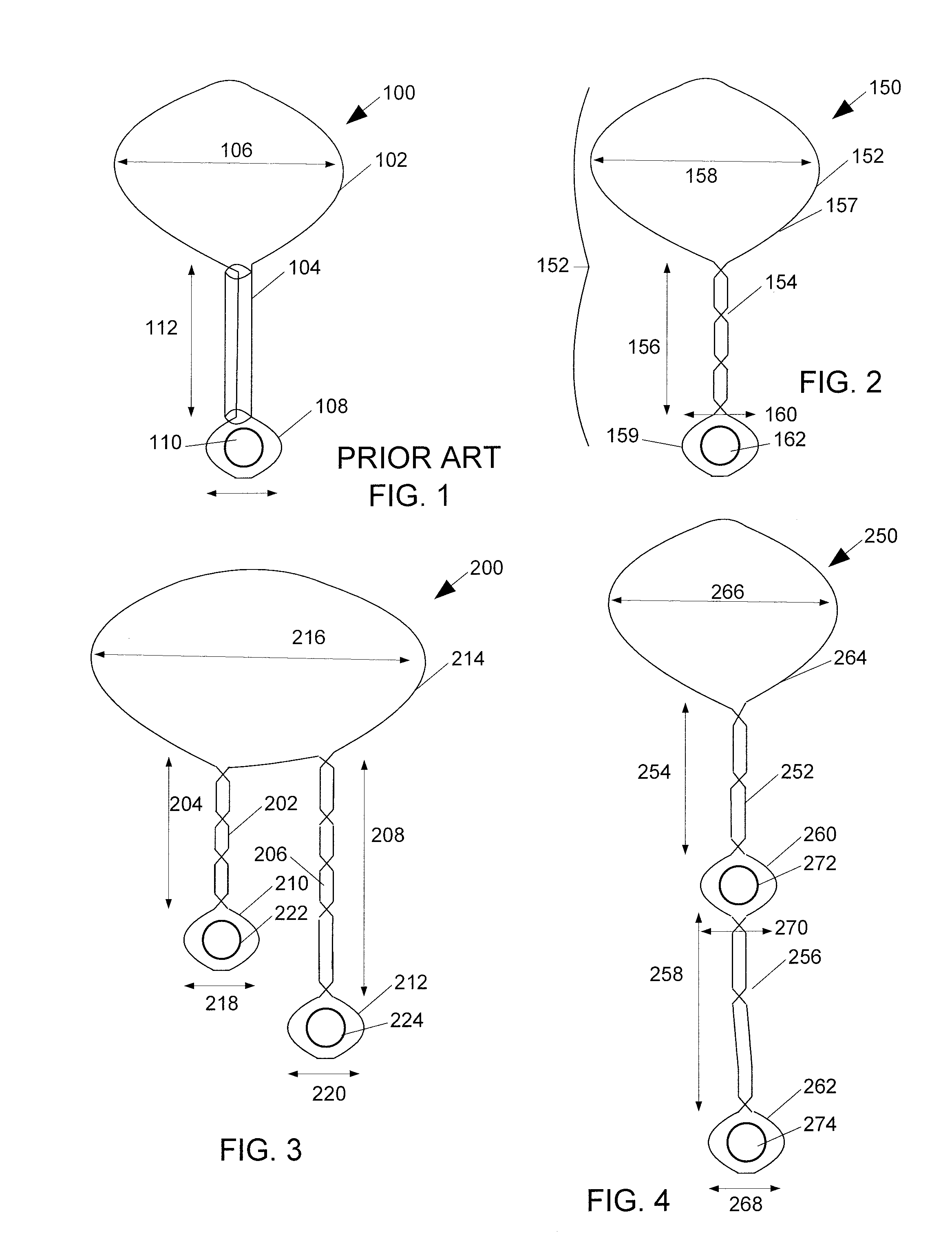
The embodiment 200 of FIG. 3 is formed similarly to that of FIG. 2, except that after forming the wire loop, it is divided and twisted into a first 202 twisted portion of a first length 204, a second 206 twisted portion of a second length 208 which may or may not be the same as the first length, a first sensor loop 210, a second sensor loop 212, and a coupling loop 214. The coupling loop 214 diameter 216 is about one centimeter as with the embodiment of FIG. 2, and the sensor loops 210, 212 are of diameter 218, 220 approximately half to one millimeter. A capsule 222, 224 of an EPR sensing material, such as LiPc and chosen as appropriate for studies to be performed with the coupler-resonator, is retained in each sensor loop 210, 212 as previously discussed.

embodiment 250

The embodiment 250 of FIG. 4 is formed similarly to that of FIG. 2, except that after forming the wire loop, it is divided and twisted into a first 252 twisted portion of a first length 254, a second 256 twisted portion of a second length 258, which may or may not be the same as the first length, a first sensor loop 260, a second sensor loop 262, and a coupling loop 264, and first and second twisted portions 252, 256. The coupling loop 264 diameter 266 is about one centimeter as with the embodiment of FIG. 2, and the sensor loops 260, 262 are of diameter 268, 270 approximately between half and one millimeter. A capsule 272, 274 of EPR sensing material, such as LiPc, is retained in each sensor loop 260, 264 as previously discussed.

While the embodiment of FIG. 4 is illustrated with two sensor loops, embodiments have been constructed with other numbers of sensor loops.

embodiment 300

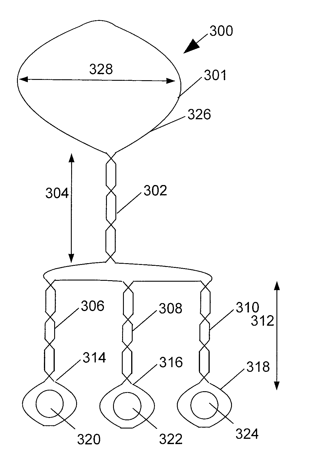
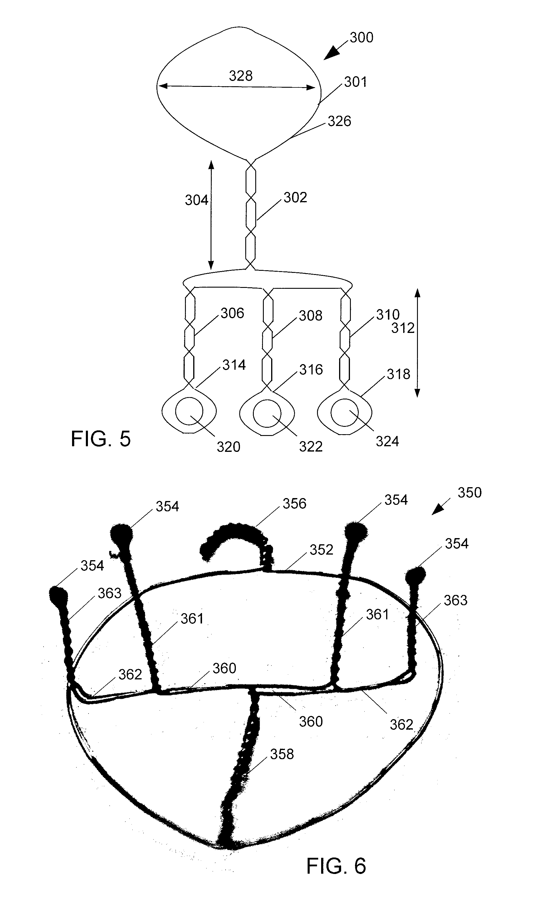
The embodiment 300 of FIG. 5 is formed similarly to that of FIG. 2, except that after forming the wire loop 301, it is divided and twisted into a first 302 twisted portion of a first length 304, then further divided into a second, third, and fourth 306, 308, 310 twisted portion, or tine portion, of a second length 312 which may or may not be the same as the first length. The tine portions 308, 310, may be of unequal length 312, and lengths 304, 312, need not be calculated based upon the wavelength of the resonance. The wire loop 301 is further formed into first, second, and third sensor loops 314, 316, and 318. A capsule 320, 322, 324 of EPR sensing material such as LiPc is retained in each sensor loop 314, 316, 318 as previously discussed. The coupling loop 326 diameter 328 is about one centimeter as with the embodiment of FIG. 2, and the sensor loops 314, 316, 318 are of diameter approximately half to one millimeter.

While the embodiment of FIG. 5 is illustrated with three sensor l...


PUM


Abstract

A coupler-resonator for electron paramagnetic resonance (EPR) spectroscopy in subjects has a wire loop formed into a coupling loop, a central transmission portion, and sensor loops. The sensor loops hold EPR sensor materials and are coated with biocompatible plastic. The coupler-resonator is implanted in a subject, the subject in a nonuniform magnetic field with a pickup coil for RF response measurement apparatus near the subject's skin and inductively coupled to the coupling loop. Resonances are measured at multiple sensor loops distinguished by sweeping magnetic field or radio frequency. A biopsy sampler has an outer needle with sensor loop and a central sampling needle with cavity for biopsy samples and EPR sensor material. A device for EPR of fingernails has sensor loops in a partial glove for holding loops next to fingertips. A device for EPR of teeth has sensor loops in plastic chips that can be held between the teeth.

Description

FIELDThe present document relates to the field of electron paramagnetic resonance (also known as electron spin resonance) spectroscopy as applied to biomedical research and medicine.BACKGROUNDWhile most molecules have paired electrons in consequence of covalent bonding, some molecules—including free radicals—have electrons that are not paired. Paired electrons have opposite spins (Ms=+ / −½) that cancel out net magnetic moments and reduce interaction with external fields. Unpaired electrons, however, have spins that can interact with magnetic fields.Unpaired electrons in molecules will resonate in a magnetic field. Electron Paramagnetic Resonance Spectroscopy (EPR), sometimes known as Electron Spin Resonance Spectroscopy, takes advantage of this effect to quantify and determine environments of the unpaired electrons. This is done by applying a magnetic field to a substance, which may be within a subject, to align spins of unpaired electrons in the substance. Once spins are aligned, a ...

Claims


Application Information

Patent Timeline
Patent Type & Authority Applications(United States)
IPC IPC(8): A61B5/055G01R33/44
CPCG01R33/286G01R33/287G01R33/34084G01R33/60G01R33/3415G01R33/58G01R33/341
Inventor SWARTZ, HAROLDLESNIEWSKI, PIOTRLI, HONG BIN
Owner THE TRUSTEES OF DARTMOUTH COLLEGE NONEPROFIT CORP
Why Eureka
Try Eureka