Pneumatic Alternating Pressure Relief of a Foot

a technology of pneumatic alternating pressure and foot, which is applied in the field of pressure relief of feet, can solve the problems dfus may present a risk of limb amputation for patients, and patients are often subject to the appearance of diabetic foot ulcers (dfu), so as to achieve the effect of relieving pressure of predetermined portions of

Inactive Publication Date: 2011-06-09
C BOOT
View PDF11 Cites 76 Cited by
  • Summary
  • Abstract
  • Description
  • Claims
  • Application Information

AI Technical Summary

Benefits of technology

[0019]In accordance with another embodiment of the disclosed technique, there is provided a device for use in a system for alternately applying and relieving pressure of predetermined portions of a foot of a user. The device is moveable between a plurality of positions. The system includes a plurality of inflatable chambers, located at predetermined locations, corresponding to the predetermined portions of the foot. The device includes a plurality of membranes, an elongated rod, having a first end and a second end, the rod being coupled with the a first membrane proximate to the first end thereof. The rod is coupled with a second membrane proximate to the second end thereof. The rod being moveable between a plurality of positions. The device also includes a plurality of fasteners, each fastener maintaining

Problems solved by technology

Diabetic patients are often subject to the appearance of Diabetic Foot Ulcers (DFU), caused due to poor vascular blood flow combined with dela

Method used


Image

  • Pneumatic Alternating Pressure Relief of a Foot
  • Pneumatic Alternating Pressure Relief of a Foot
  • Pneumatic Alternating Pressure Relief of a Foot

Examples


Embodiment Construction

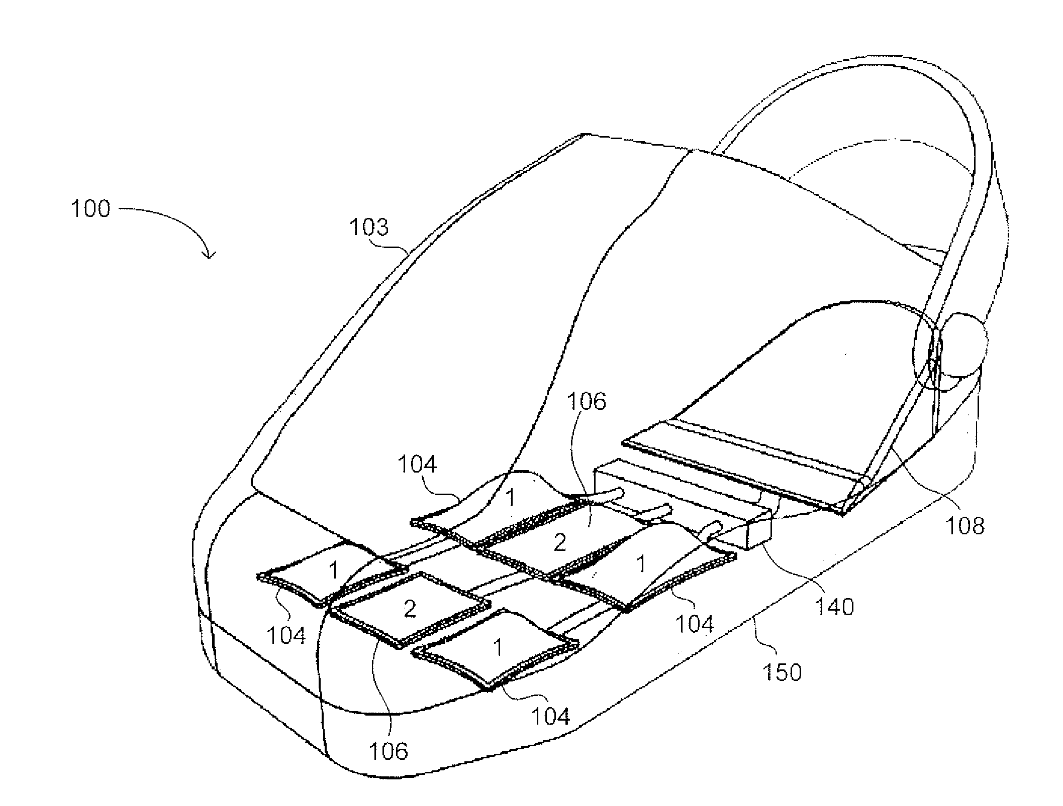
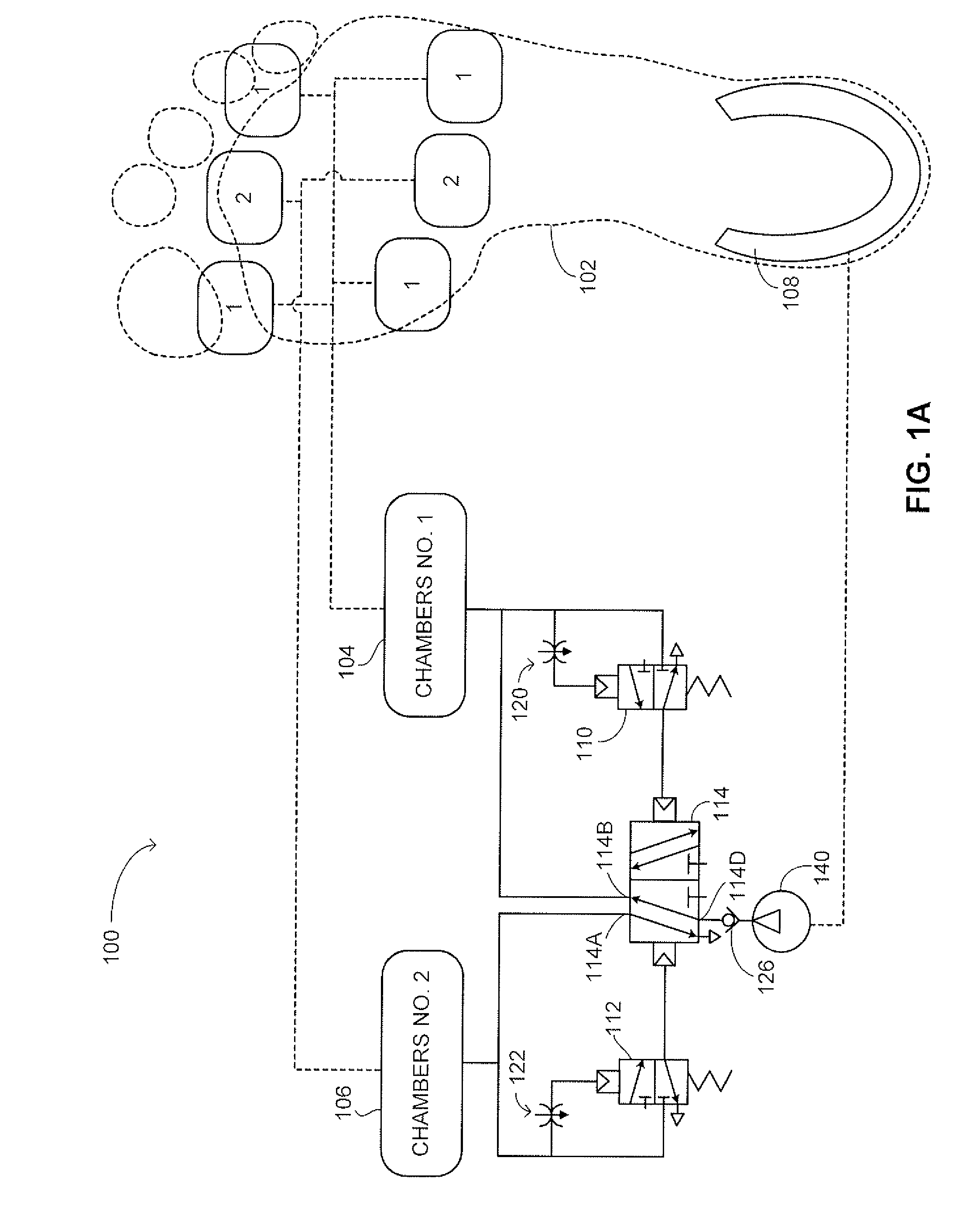
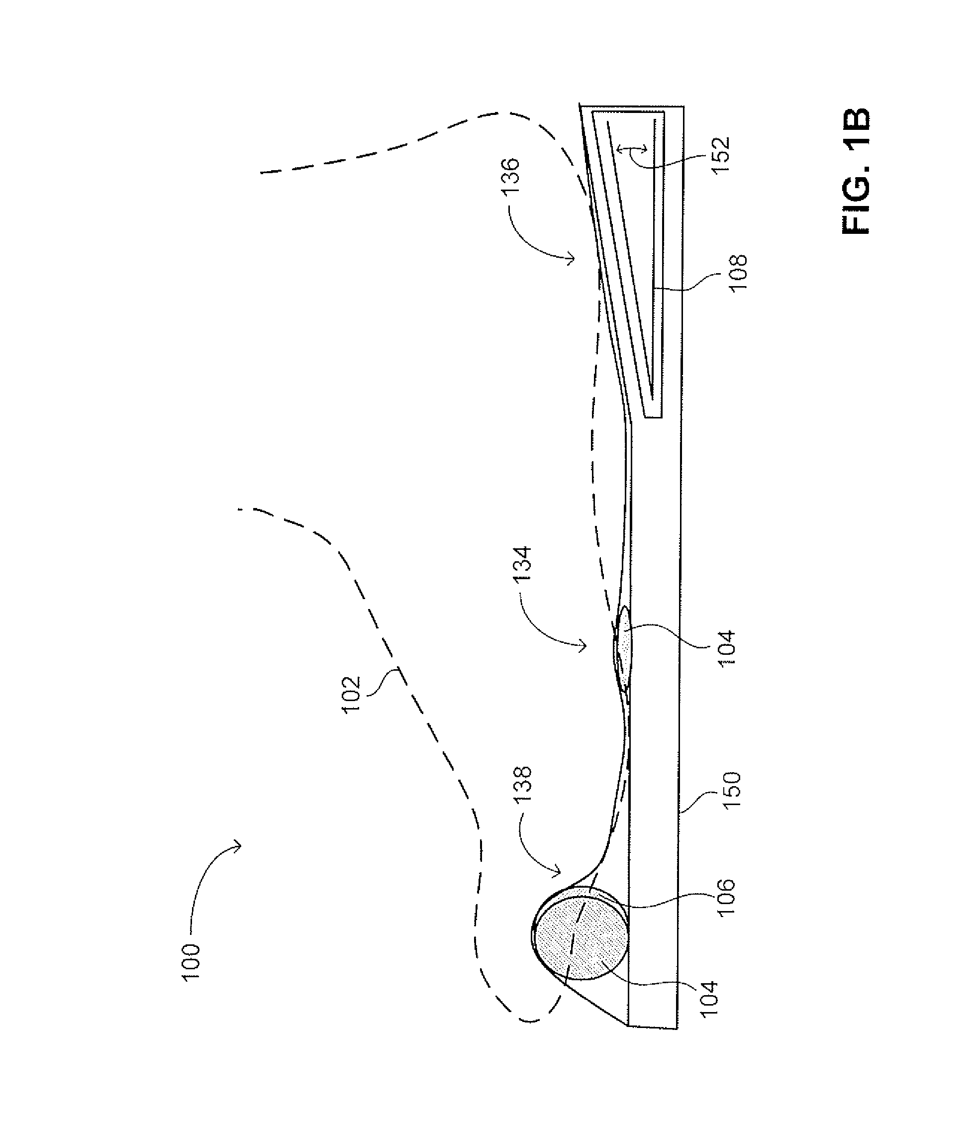
[0039]The disclosed technique overcomes the disadvantages of the prior art by providing a system and method for pressure relief portions of a foot of a user, by alternately applying and relieving pressure of selected portions of a user's foot during walking, using alternating pneumatic pressure. The system includes a plurality of inflatable chambers, possibly arranged in groups of chambers. Each chamber or group of chambers is inflated and deflated alternately, for example, by a respective pneumatic valve. Air is supplied to inflate the chambers by a manual pump coupled with an elastic flexible element (e.g., a spring or other specific self retained geometry) located below the heel portion of the foot. The walking action of the user operates on the flexible element to activate the pump (e.g., pressing the flexible element), thereby providing a self-powered compression system.

[0040]Reference is now made to FIGS. 1A, 1B and 1C. FIG. 1A is a schematic illustration of a system, generall...


PUM


Abstract

A system for alternately applying and relieving pressure of predetermined portions of a foot of a user. The system includes a plurality of inflatable chambers, located at predetermined locations, corresponding to the predetermined portions of the foot and a pump. The system also includes a center pneumatic valve, coupled with the pump and with the inflatable chambers, for receiving air from the pump and inflating at least one of the inflatable chambers. The system further includes a pneumatic valve assembly, coupled with the center pneumatic valve. The pneumatic valve assembly is coupled with at least a respective one of the inflatable chambers. The pneumatic valve assembly is moveable between two positions, and changes position when a predetermined pressure value is achieved in the corresponding inflatable chamber. When the pneumatic valve assembly changes position, the center pneumatic valve changes position, thereby inflating another inflatable chamber.

Description

REFERENCE TO RELATED APPLICATIONS[0001]This application claims the benefit of and priority to co-pending U.S. Patent Application Ser. No. 61 / 266,317, filed Dec. 3, 2009, the entire disclosure of which is incorporated by reference herein.FIELD OF THE INVENTION[0002]The disclosed technique relates to pressure relief of a foot of a user, in general, and to methods and systems for relieving pressure of selected portions of a user's foot during walking, using alternating pneumatic pressure to alternately inflate and deflate predetermined chambers, in particular.BACKGROUND[0003]The action of treading, walking, running and the like causes pressure appliance on certain portions of the walker's foot. The location of these portions is substantially constant, depending on the shape of the walker's foot, the shoe and the sole, and the type of activity performed (i.e., walking, treading, running, jumping and the like). Shoes and shoe soles for pressure relief of certain portions of the foot are ...

Claims


Application Information

Patent Timeline
IPC IPC(8): A61F5/34
CPCA43B13/203A43B13/186A43B3/34
Inventor BALLIN, BENNYCALDERON, NOAMSALMAN, ALEXANDER
Owner C BOOT
Why Eureka
Try Eureka