Intake system including vacuum aspirator

a vacuum aspirator and vacuum technology, applied in the direction of combustion engine, combustion air/fuel air treatment, charge feed system, etc., can solve the problems of increasing overall vehicle cost, parasitic fuel economy loss, and engine downsizing, so as to reduce the ability of these engines to provide brake booster vacuum and increase the overall vehicle cost

Inactive Publication Date: 2011-06-09
FORD GLOBAL TECH LLC
View PDF23 Cites 178 Cited by
  • Summary
  • Abstract
  • Description
  • Claims
  • Application Information

AI Technical Summary

Benefits of technology

[0002]Spark-ignited vehicles may use intake manifold vacuum to provide brake boost or power assist. Engine downsizing reduces the ability of these engines to provide brake booster vacuum. One existing solution is to add a vacuum pump, however the vacuum pump leads to parasitic fuel economy losses and increases overall vehicle cost.
[0008]One advantage of the above examples is that excess compressor pressure and flow is used to generate vacuum. In this way, downsized engines including a turbocharger or supercharger may generate vacuum, even during cold start. Further, an example throttle including a first inlet and a second inlet may control flow through an example aspirator, as well as flow to an example manifold not from the aspirator, simplifying an intake system configuration. In examples including a plurality of aspirators one of the plurality may be configured for high flow and another may be configured for low flow, increasing an intake system's efficiency at generating vacuum over a wide pressure range.

Problems solved by technology

Engine downsizing reduces the ability of these engines to provide brake booster vacuum.
One existing solution is to add a vacuum pump, however the vacuum pump leads to parasitic fuel economy losses and increases overall vehicle cost.
During cold start, engine conditions (such as high manifold air pressure and low barometric pressure due to low temperature and / or high altitude) may limit the available vacuum for various engine systems, such as the brake booster.
Intake systems including a single fixed geometry aspirator may function inefficiently or not at all at some pressures of the increased pressure range.
In this way, downsized engines including a turbocharger or supercharger may generate vacuum, even during cold start.

Method used


Image

  • Intake system including vacuum aspirator
  • Intake system including vacuum aspirator
  • Intake system including vacuum aspirator

Examples


Embodiment Construction

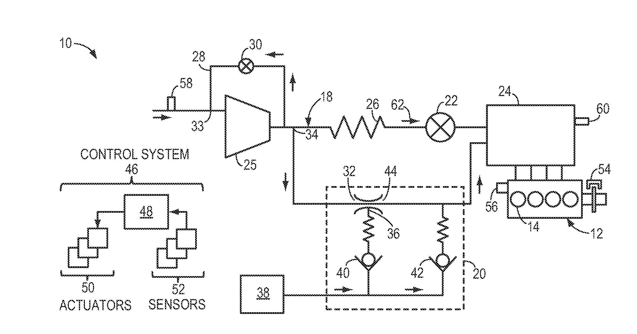
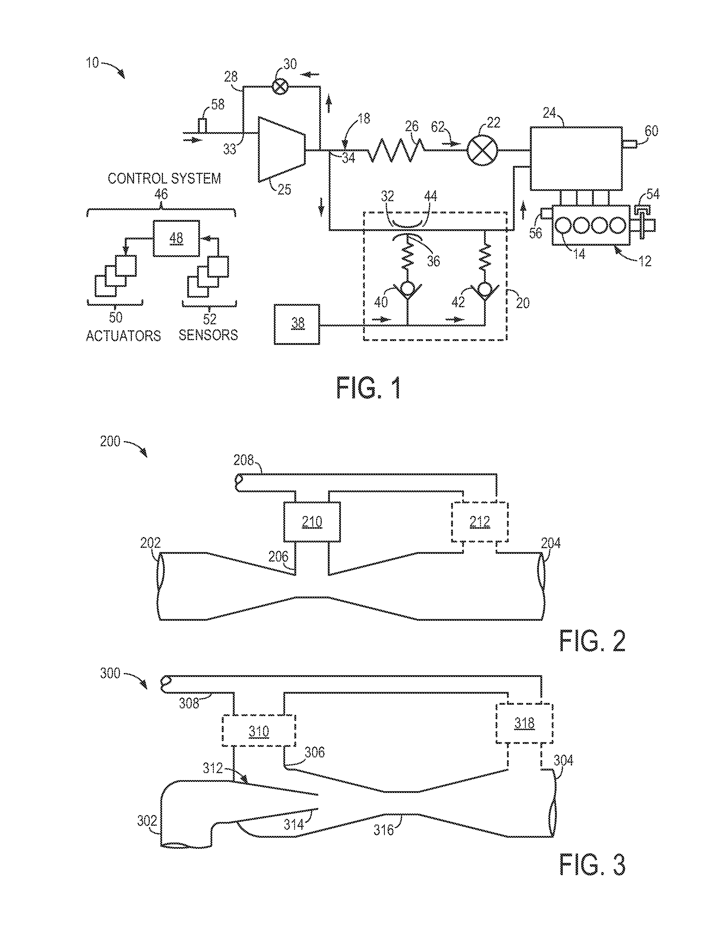
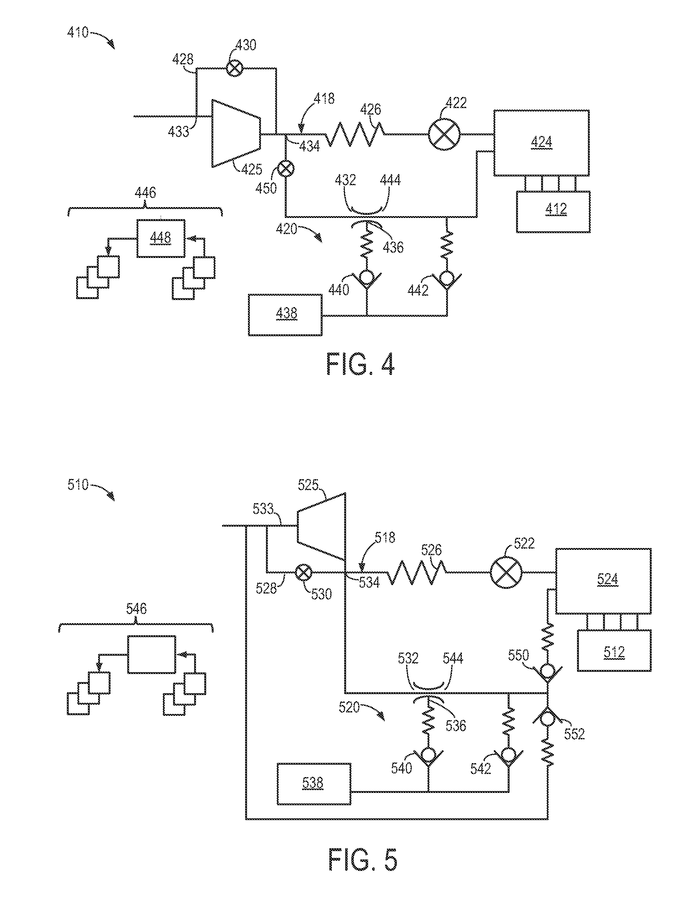
[0020]A first example intake system for an engine is described, with respect to FIG. 1, to introduce possible devices, arrangements and configurations of an intake system including an aspirator. Example aspirators are discussed in more detail with respect to FIGS. 2 and 3. Additional example intake systems are described with respect to FIGS. 4-7 and 10. FIGS. 8 and 9 show an example passive control valve included in some example intake systems. An example throttle included in example intake systems is discussed with respect to FIG. 10-12. Finally, multi-aspirator intake systems are described with respect to FIGS. 13-18. Integration of example intake systems with additional engine systems, such as fuel vapor purge and positive crankcase ventilation systems, is discussed with respect to FIGS. 19 and 20.

[0021]FIG. 1 shows a first example intake system 10 for an engine 12. In the present example, engine 12 is a spark-ignition engine of a vehicle, the engine including a plurality of cyli...


PUM


Abstract

In some examples, reduced engine displacement reduces an engine's ability to provide brake booster vacuum. The present application relates to intake systems including a vacuum aspirator to generate vacuum.

Description

TECHNICAL FIELD [0001]The present application relates to intake systems including a vacuum aspirator, for generating vacuum for use in a brake booster, for example.BACKGROUND AND SUMMARY [0002]Spark-ignited vehicles may use intake manifold vacuum to provide brake boost or power assist. Engine downsizing reduces the ability of these engines to provide brake booster vacuum. One existing solution is to add a vacuum pump, however the vacuum pump leads to parasitic fuel economy losses and increases overall vehicle cost.[0003]In one approach described in U.S. Pat. No. 7,610,140, a vehicle ejector system has an ejector, a state change device that causes the ejector to function or stop functioning, and a control device that controls the state change device (Summary). “Furthermore . . . the control device may include a control prohibition portion that prohibits the control device from controlling the state change device so as to cause the ejector to function if water temperature of a cooling...

Claims


Application Information

Patent Timeline
Patent Type & Authority Applications(United States)
IPC IPC(8): F02M35/10
CPCF02M35/10229F02B37/00F02D9/08F02D31/005
Inventor PURSIFULL, ROSS DYKSTRAULREY, JOSEPH NORMAN
Owner FORD GLOBAL TECH LLC
Why Eureka
Try Eureka