Thickness measuring device of laminating machine

a laminating machine and thickness measurement technology, applied in the direction of mechanical control devices, process and machine control, instruments, etc., can solve the problems of inconvenient operation and the lack of practical use of prior art, and achieve the effect of increasing the overall raising or lowering the heating temperature, and increasing the usefulness and convenience of the laminating machin

Inactive Publication Date: 2011-06-09
TEX YEAR INDS
View PDF2 Cites 6 Cited by
  • Summary
  • Abstract
  • Description
  • Claims
  • Application Information

AI Technical Summary

Benefits of technology

[0005]The primary objective of the present invention is to provide a thickness measuring device of a laminating device, wherein the thickness measuring device is composed of a mount, a stepper motor, a screw rod, a first contact-activated element, a second contact-activated element, and a microcontroller unit, and wherein measurement is conducted via pulse signals that control the stepper motor. More specifically, the high level (logical 1), low level (logical 0), positive edges, or negative edges of the pulse signals are detected by an electronic signal detection method so as to trigger a counting process. As the count that corresponds to one complete turn of a thread of the screw rod is pre-defined, and the precision of axial distance of the screw rod is known, the counts obtained can be converted into a thickness measurement (thickness=C0−C1). Thus, the thickness of an object to be detected can be measured conveniently, thereby increasing the usefulness and ease of operation of the laminating machine as a whole. Another objective of the present invention is to provide the foregoing thickness detecting device of a laminating machine, wherein the thickness measurement is sent to the microcontroller unit for being judged by a firmware, such that the thickness measurement is either sent to a heater so as to raise or lower the heating temperature, or used to change the rotating speed of a motor. Then, a guide roller set is activated to rotate forward, thereby guiding a piece of paper through a lamination process. Hence, the temperature setting of the laminating machine and the rotating speed of the motor can be selected according to the thickness measurement, thereby increasing the overall usefulness and convenience of the laminating machine.

Problems solved by technology

Moreover, with the man-machine interface of a conventional laminating machine, a user has to select the desired laminating film thickness and the type of to-be-laminated object by pressing keys, which is rather inconvenient.
Therefore, the prior art still leaves much to be desired in practical use.

Method used


Image

  • Thickness measuring device of laminating machine
  • Thickness measuring device of laminating machine
  • Thickness measuring device of laminating machine

Examples


Embodiment Construction

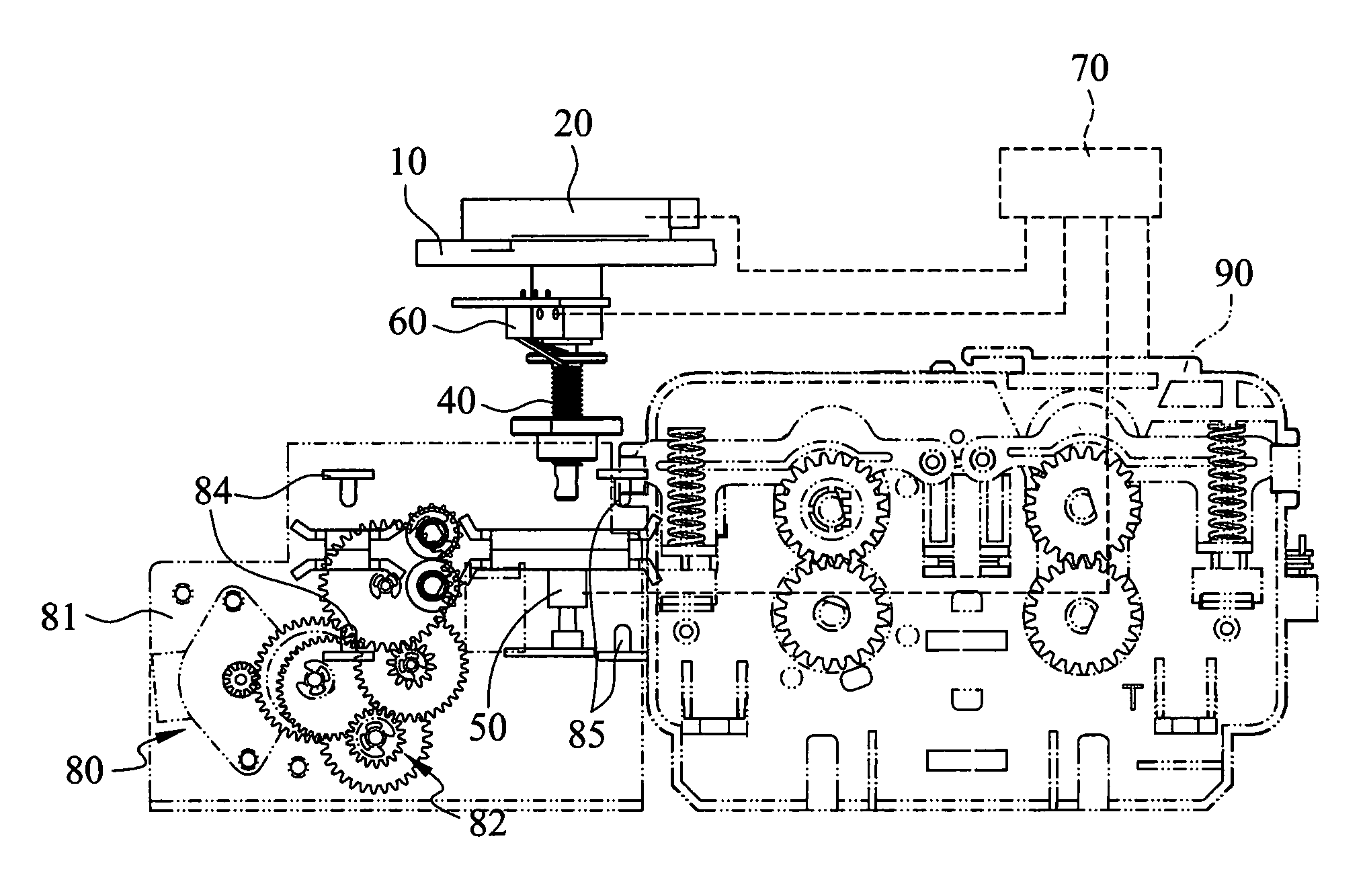
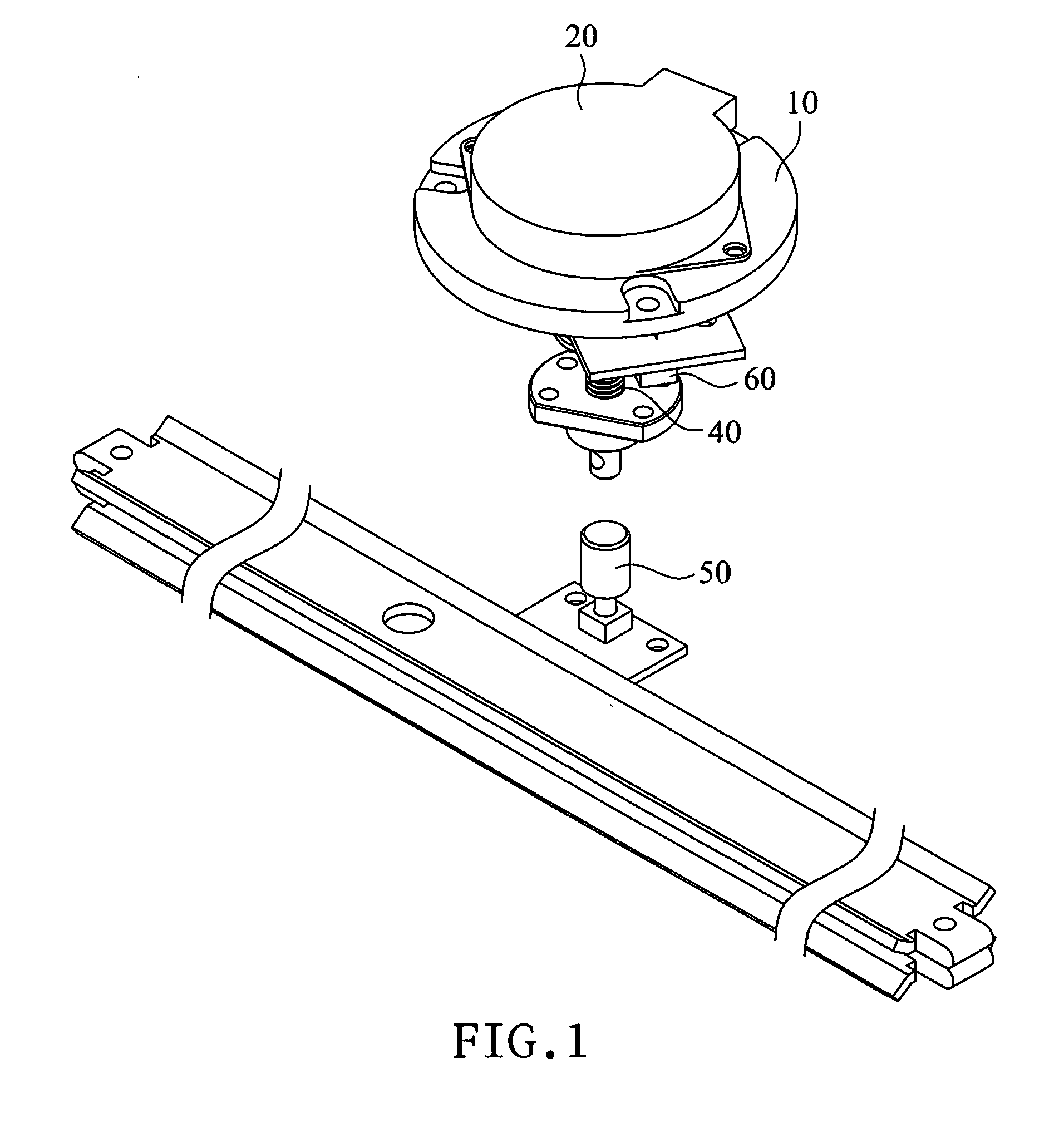
[0013]According to an embodiment of the present invention as shown in FIGS. 1 through 5, a thickness measuring device of a laminating machine includes a mount 10, a stepper motor 20, a screw rod 40, a first contact-activated element 50, a second contact-activated element 60, and a microcontroller unit (MCU) 70.

[0014]The stepper motor 20 is coupled to the mount 10. The stepper motor 20 is controlled and driven by pulse signals.

[0015]The screw rod 40 is interlocked with the stepper motor 20 so as to be moved vertically up and down.

[0016]The first contact-activated element 50 is provided at a position corresponding to and some distance below the screw rod 40. The first contact-activated element 50 is a contact switch.

[0017]The second contact-activated element 60 is provided at a position corresponding to and some distance above the screw rod 40. The second contact-activated element 60 is a contact switch.

[0018]The microcontroller unit 70 is electrically connected to the stepper motor 2...


PUM

PropertyMeasurementUnit
temperatureaaaaaaaaaa
axial distanceaaaaaaaaaa

Abstract

A thickness measuring device of a laminating machine includes a mount, a stepper motor, a screw rod, a first contact-activated element, a second contact-activated element, and a microcontroller unit. The stepper motor is coupled to the mount. The screw rod is interlocked with the stepper motor. The first contact-activated element is provided at a position corresponding to and some distance below the screw rod. The second contact-activated element is provided at a position corresponding to and some distance above the screw rod. The microcontroller unit is electrically connected to the stepper motor, the first contact-activated element, and the second contact-activated element so as to provide initialization setting and exercise judgment and control after receiving a thickness measurement. Thus, the thickness of an object to be detected can be conveniently measured.

Description

BACKGROUND OF THE INVENTION[0001]1. Technical Field[0002]The present invention relates to a thickness measuring device of a laminating machine and, more particularly, to a thickness measuring device which is composed of a mount, a stepper motor, a screw rod, a first contact-activated element, a second contact-activated element, and a microcontroller unit; configured for measuring the thickness of a to-be-detected object in a convenient manner; and applicable to various kinds of laminating machines or the like.[0003]2. Description of Related Art[0004]Generally, the thickness of paper is measured to the accuracy of a fraction of a millimeter. When a piece of paper is heated by a laminating machine during the lamination process, a 0.5-mm difference in paper thickness may result in a temperature difference up to 50° C. Hence, it has been an important goal in the field of laminating machines to develop an electronic design that enables precise thickness measurement, features convenient o...

Claims


Application Information

Patent Timeline
Patent Type & Authority Applications(United States)
IPC IPC(8): B32B41/00
CPCB32B41/00G01B7/06G01B5/06
Inventor CHAO, MEI-LIENSU, YANG-CHIH
Owner TEX YEAR INDS
Why Eureka
Try Eureka