Dialysis system with ultrafiltration control

a technology of ultrafiltration control and dialysis system, which is applied in the direction of filtration separation, separation process, instruments, etc., can solve the problems of large dialysis system size, unsuitable for use in patients' homes, and inability to move fluid from dialysate, etc., to achieve precise control of ultrafiltration level, reduce water consumption, and improve the effect of filtration efficiency

Active Publication Date: 2011-06-09
OUTSET MEDICAL
View PDF17 Cites 134 Cited by
  • Summary
  • Abstract
  • Description
  • Claims
  • Application Information

AI Technical Summary

Benefits of technology

In view of the foregoing, there is a need for improved dialysis systems that are smaller, more portable, consume less water and that provide precise control over a level of ultrafiltration. Disclosed are systems and methods for performing hemodialysis that include fluid handling systems and provide accurate control over the type and level of hemodialysis being performed. The system includes a first pump for pumping dialysate into a dialyzer and a second pump for pumping dialysate out of the dialyzer. The system also includes a third pump that provides improved control of a level of ultrafiltration, hemodiafiltration, or both, as described in detail below.

Problems solved by technology

In some circumstances, by design or unintentionally, fluid in the dialysate compartment is higher than the blood compartment, causing fluid to move from the dialysate compartment into the blood compartment.
Unfortunately, current dialysis systems are large in size, making them generally unsuitable for use in a patient's home.
Current dialysis systems are also energy-inefficient in that they use large amounts of energy and require enormous amounts of water for proper use.
Although some home dialysis systems are available, they generally use complex flow-balancing technology that is relatively expensive to manufacture and most systems are designed with a system of solenoid valves that create high noise levels.

Method used


Image

  • Dialysis system with ultrafiltration control
  • Dialysis system with ultrafiltration control
  • Dialysis system with ultrafiltration control

Examples


Embodiment Construction

In order to promote an understanding of the principals of the disclosure, reference is made to the drawings and the embodiments illustrated therein. Nevertheless, it will be understood that the drawings are illustrative and no limitation of the scope of the disclosure is thereby intended. Any such alterations and further modifications in the illustrated embodiments, and any such further applications of the principles of the disclosure as illustrated herein are contemplated as would normally occur to one of ordinary skill in the art.

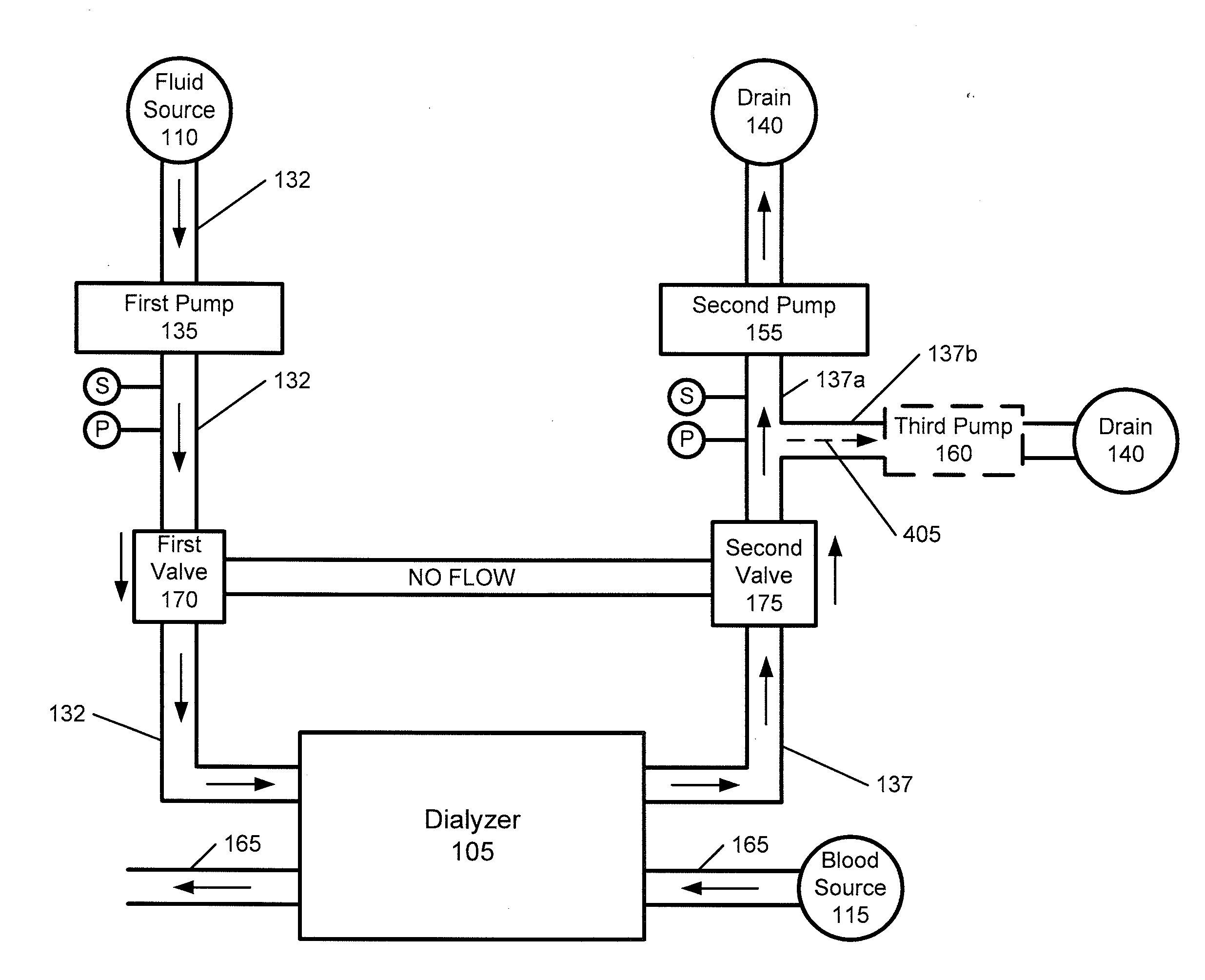
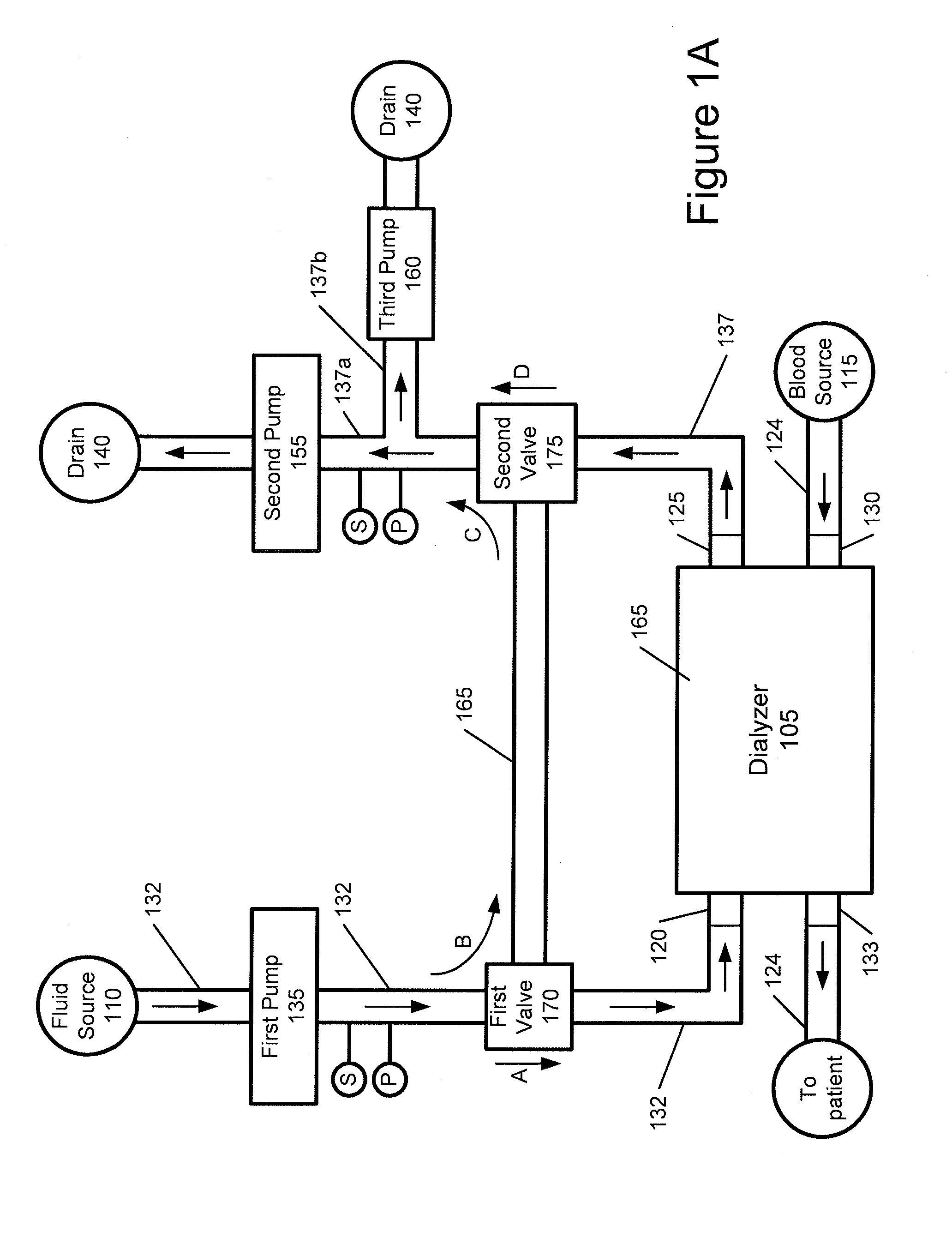
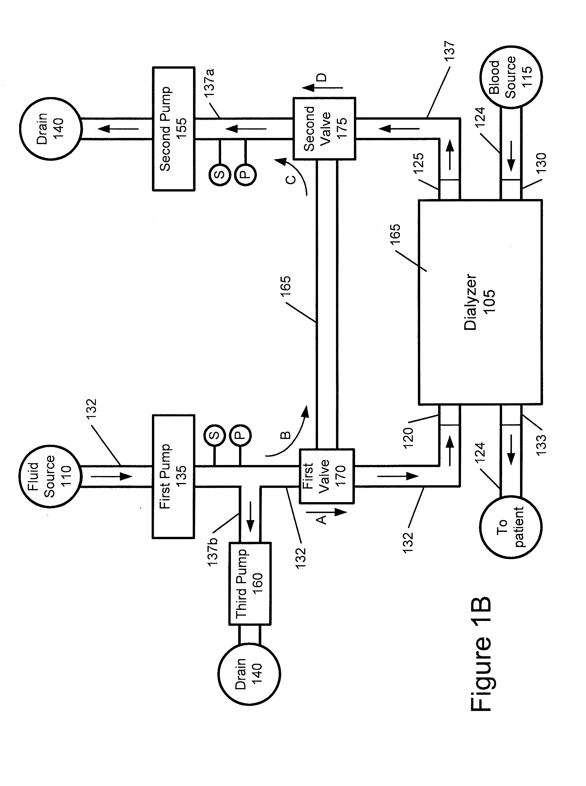
FIG. 1A shows a schematic view of a dialysis system adapted to perform hemodialysis of a patient's blood. The system includes an arrangement of three or more pumps that provide improved control over the type of hemodialysis being performed. By varying the relative pump speeds of the three pumps, an operator can vary the level of blood filtration and can also selectively achieve ultrafiltration and hemodiafiltration of the blood.

Ultrafiltration is a proces...


PUM

PropertyMeasurementUnit
flow rateaaaaaaaaaa
flow rateaaaaaaaaaa
flow rateaaaaaaaaaa

Abstract

Systems and methods are disclosed for performing hemodialysis that include fluid handling systems that provide accurate control over the type and level of hemodialysis being performed. The system includes a first pump for pumping dialysate into a dialyzer and a second pump for pumping dialysate out of the dialyzer. The system also includes a third pump that provides improved control of a level of ultrafiltration, hemodiafiltration, or both.

Description

BACKGROUNDChronic dialysis has been performed on patients with kidney failure since the early 1960's. A dialyzer is a device for cleansing blood through hemodialysis by a process of diffusion and / or convection of waste products, dissolved solutes and fluid from the blood across a semi permeable membrane into a dialysis solution known as dialysate. A dialysis system is an assembly that includes the dialyzer and associated equipment to support the dialyzer, such a plumbing and pumps.Diffusion is the principal mechanism in which dialysis removes waste products such as urea, creatinine, phosphate and uric acid, among others, from the blood. A differential between the chemical composition of the dialysate and the chemical composition of the blood causes the waste products to be drawn through the semi-permeable membrane from the blood into the dialysate. Ultrafiltration is a process in dialysis where fluid is caused to move across the membrane from the blood into the dialysate for the pur...

Claims


Application Information

Patent Timeline
Patent Type & Authority Applications(United States)
IPC IPC(8): B01D61/32B01D61/24
CPCA61M1/16A61M1/3413A61M1/1619A61M1/1601A61M1/165A61M1/3427A61M1/1647A61M1/3403A61M1/34A61M2205/3334A61M2205/3331A61M2205/70A61M2205/702G05D7/0676
Inventor CURTIS, JAMES R.NONN, LADISLAUS F.WRAZEL, JULIE
Owner OUTSET MEDICAL
Why Eureka
Try Eureka