Method and arrangement for detecting a surface of an object

a surface detection and object technology, applied in the direction of fluorescence/phosphorescence, measurement devices, instruments, etc., can solve the problems of only analyzing the surface of the object from which the reflection propagates with difficulty, affecting the detection accuracy of the structure deriving back to the radiation pattern in the picture, and disturbing reflections, etc., to achieve suppressing the intensity noise (speckle noise) and reducing the difficulty of detection

Inactive Publication Date: 2011-06-09
MTU AERO ENGINES GMBH
View PDF7 Cites 2 Cited by
  • Summary
  • Abstract
  • Description
  • Claims
  • Application Information

AI Technical Summary

Benefits of technology

[0013]It has also been shown that in accordance with the disclosure, intensity noise (speckle noise) is suppressed. The classic case of fluorescence is that ultraviolet light is irradiated, and light in the visible range is received for recording of pictures. As compared to irradiation likewise in visible light, higher measurement accuracy is achieved by use of the shorter-wavelength ultraviolet light.
[0014]To suppress reflections with particular effectiveness, provision can be made that when the emitted radiation is received, a filter is used for filtering out the radiation from the first wavelength range. By this means, impairment of measurement (or detection of the surface) is reliably avoided if impinging light is not absorbed by the film made of fluorescing material, but rather is reflected. The filter can extend over the entire wavelength range in which the electromagnetic radiation is absorbed, but it suffices to design it so that it filters out precisely those wavelengths at which the surface is irradiated. The latter can be a portion of the first wavelength range; for example, if a laser is used for the irradiation, an exact wavelength can be set.
[0015]In a preferred embodiment form, the fluorescing material includes a solvent with a fluorescing dye in solution. Such a fluorescence medium is permitted for all engine parts, and especially has an advantage of being light and easily washed off. Included then in the process is also washing the film off the surface after the analysis. The fluorescing material is particularly efficient if, in addition to the solvent and the fluorescing dye, it includes esters and surfactants.

Problems solved by technology

The result has been that with optical detection of a surface of numerous objects, for example metallic objects, which engine parts are, disturbing reflections occur.
Owing to the reflections, detection of the structures deriving back to the radiation pattern in the pictures becomes difficult, and the place on the surface of the object from which the reflection propagates is only analyzed with difficulty.
However, only certain diffusely scattering layers can be applied on engine parts, because they require authorization.
It is time-consuming to apply the layers.
They also are applied on the thickness, which impairs the precision of surface analysis.
Diffusely scattering layers also cannot suppress intensity noise, often designated as speckle noise.
Lastly, diffusely scattering layers must be removed, which is very difficult.

Method used


Image

  • Method and arrangement for detecting a surface of an object
  • Method and arrangement for detecting a surface of an object

Examples


Embodiment Construction

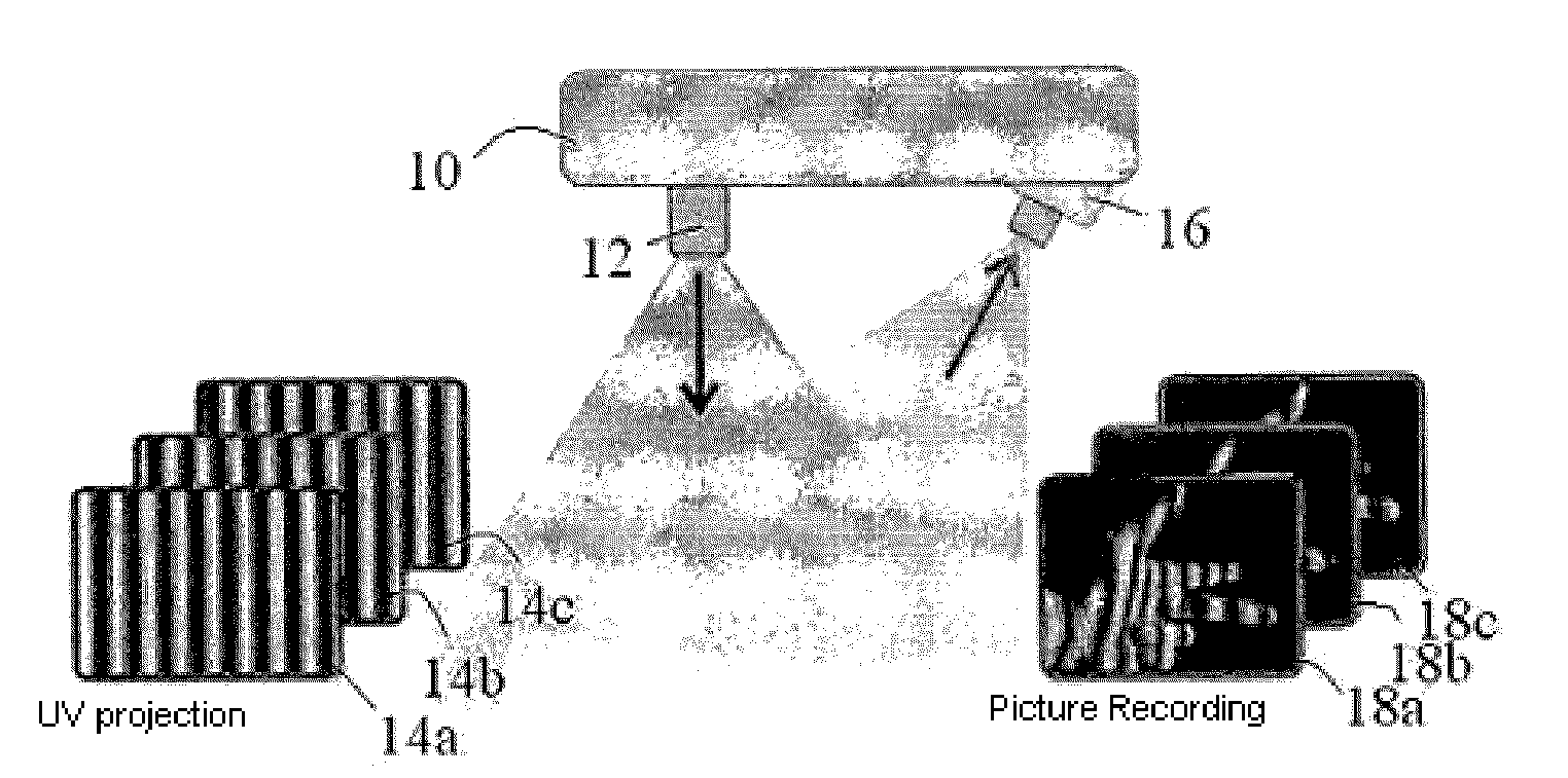
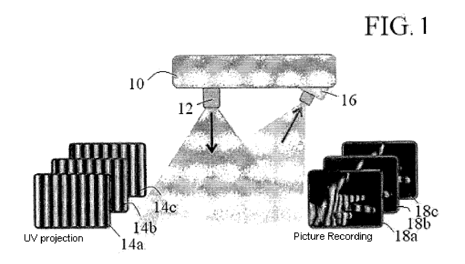
[0024]In what follows, a preferred embodiment form of the invention is described while referring to the drawing, with the FIGURE illustrating a disclosure-specific arrangement for detection of the surface of an object and the emitted and received pattern.

[0025]An arrangement given the overall designation of 10 for optical detection of the surface of an object has a radiation pattern projection device 12 which emits ultraviolet radiation which impresses a pattern. Shown as an example is a striped pattern 14a, with the intensity of the radiation being modulated perpendicular to the course of the strip in sine-wave fashion, and remaining spatially constant along the strip length. The radiation pattern undergoes a temporal variation, i.e., the strips migrate. Striped patterns 14b and 14c that temporally follow striped pattern 14a are also shown in the FIGURE.

[0026]Since ultraviolet radiation is used here to generate striped patterns 14a, 14b and 14c, fundamentally recourse can be had wh...


PUM

PropertyMeasurementUnit
wavelength rangeaaaaaaaaaa
reflectivityaaaaaaaaaa

Abstract

The invention relates to a method for optically detecting surfaces wherein strip patterns are projected onto the surface, images are captured, and the three-dimensional contour thereof is determined from the reproduction of the strip pattern on the surface of the object. The aim of the invention is to prevent reflections that interfere with the images and as a result, the surface of the object is covered with a layer of a fluorescent material, is then radiated with ultraviolet radiation, and the radiation emitted by the fluorescent material in the visible light is detected.

Description

CROSS-REFERENCE TO RELATED APPLICATIONS[0001]This application is a U.S. National Phase application submitted under 35 U.S.C. §371 of Patent Cooperation Treaty application serial no. PCT / DE2008 / 000967, filed 6 Jun. 2008, and entitled METHOD AND ARRANGEMENT FOR DETECTING A SURFACE OF AN OBJECT, which application claims priority to German patent application serial no. 10 2007 029 440.0, filed 26 Jun. 2007, and entitled VERFAHREN UND ANORDNUNG ZUM ERFASSEN EINER OBERFLÄCHE EINES OBJEKTS, the specifications of which are incorporated herein by reference in their entireties.TECHNICAL FIELD[0002]The invention relates to a method as well as an arrangement for detecting the surface of an object, with the main interest presently being detecting surfaces of engine parts, especially for aircraft. Typically investigations must especially be made of the surfaces of turbine blades.BACKGROUND[0003]The detection is optical: a radiation pattern is projected onto the surface, than then a picture of the...

Claims


Application Information

Patent Timeline
Patent Type & Authority Applications(United States)
IPC IPC(8): G01N21/64
CPCG01B11/0666G01B11/2518G01B11/2513
Inventor BAMBERG, JOACHIMHOFLING, ROLANDSATZGER, WILHELM
Owner MTU AERO ENGINES GMBH
Why Eureka
Try Eureka