Eureka AIR delivers breakthrough ideas for toughest innovation challenges, trusted by R&D personnel around the world.

Kinetic energy recycling system for usable electric and hydraulic power generation

a technology of usable electric and hydraulic power generation, applied in renewable energy generation, greenhouse gas reduction, final product manufacturing, etc., can solve the problem of limitless potential energy sources that could be utilized in this process for recycling, and achieve the effect of increasing demand and lessening energy demand

Inactive Publication Date: 2011-06-09
STILES ROBERT A
View PDF1 Cites 9 Cited by
  • Summary
  • Abstract
  • Description
  • Claims
  • Application Information

AI Technical Summary

Benefits of technology

[0018]This process will allow us to create usable energy by recycling the kinetic energy that is created by agriculture and industry utilizing man-made motion systems every day. The creation of this usable energy will have no hazardous impact on the environment. It will give us the ability to lessen the energy demand on our public energy supply grid.

Problems solved by technology

The potential energy sources that could be utilized this process for recycling is limitless.

Method used


Image

  • Kinetic energy recycling system for usable electric and hydraulic power generation
  • Kinetic energy recycling system for usable electric and hydraulic power generation
  • Kinetic energy recycling system for usable electric and hydraulic power generation

Examples


Embodiment Construction

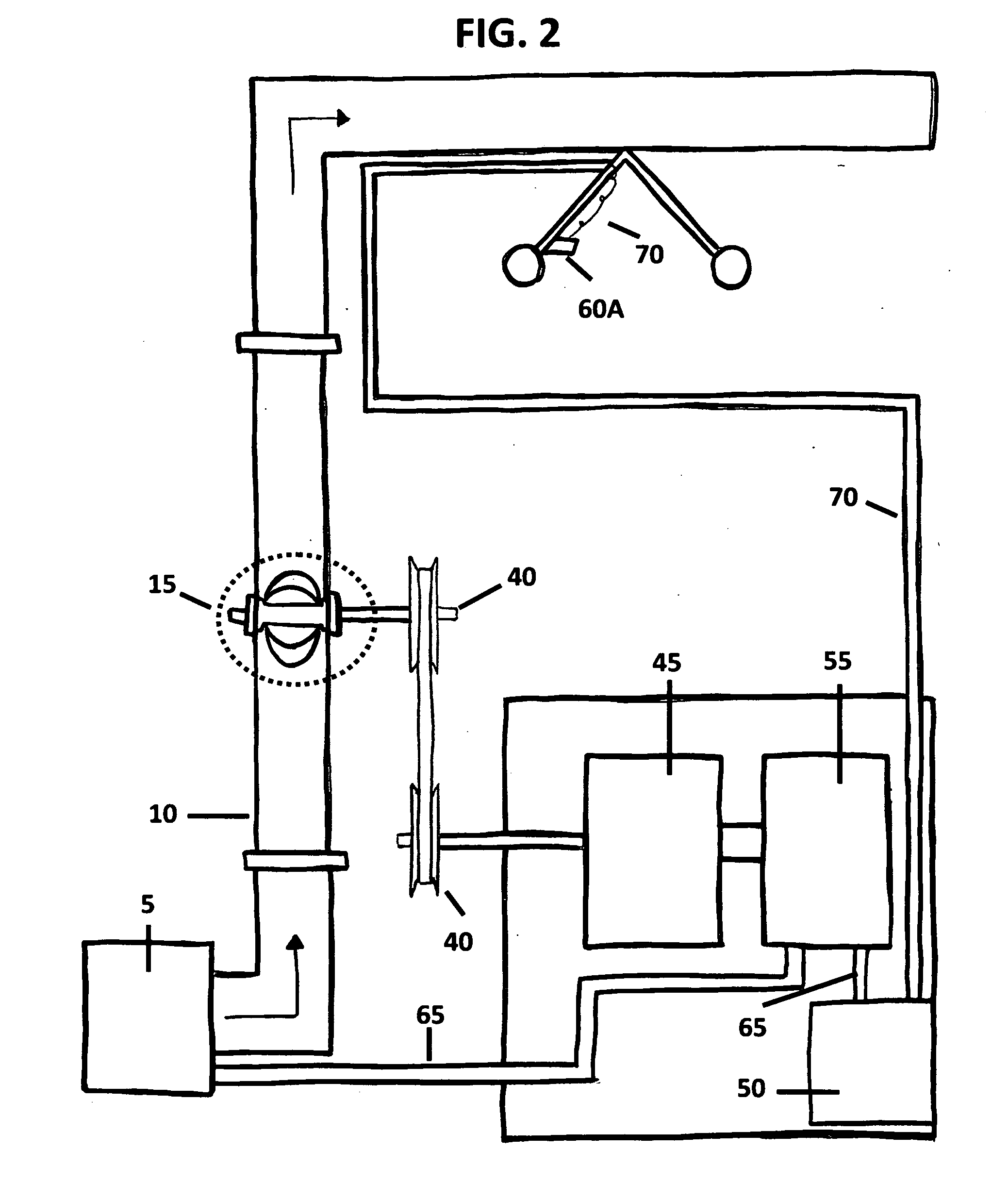
[0048]The preferred embodiment shall be described in the terms of the FIGS. 1-5. Identical elements contained in various figures are designated with the same numeral in each figure.

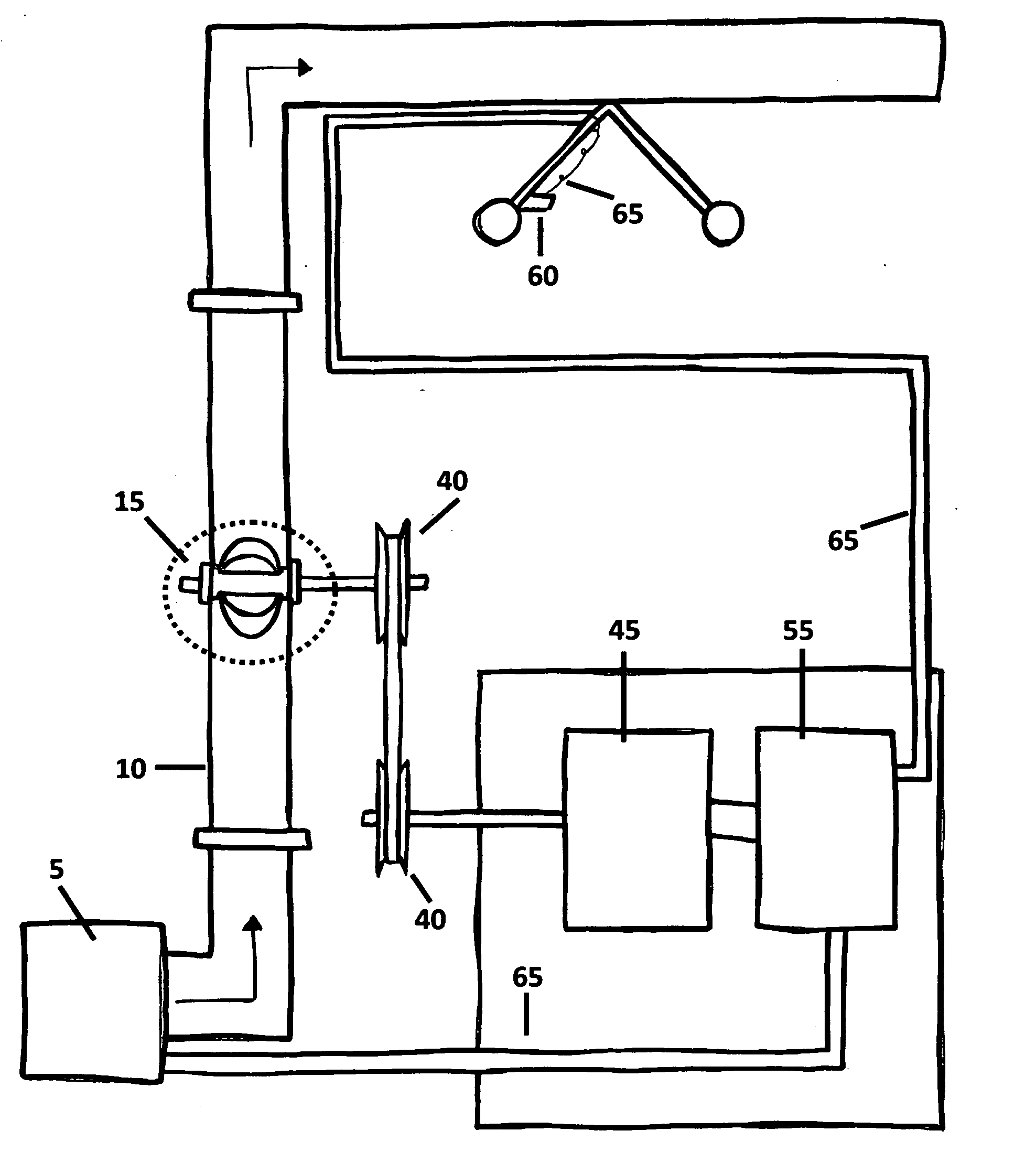
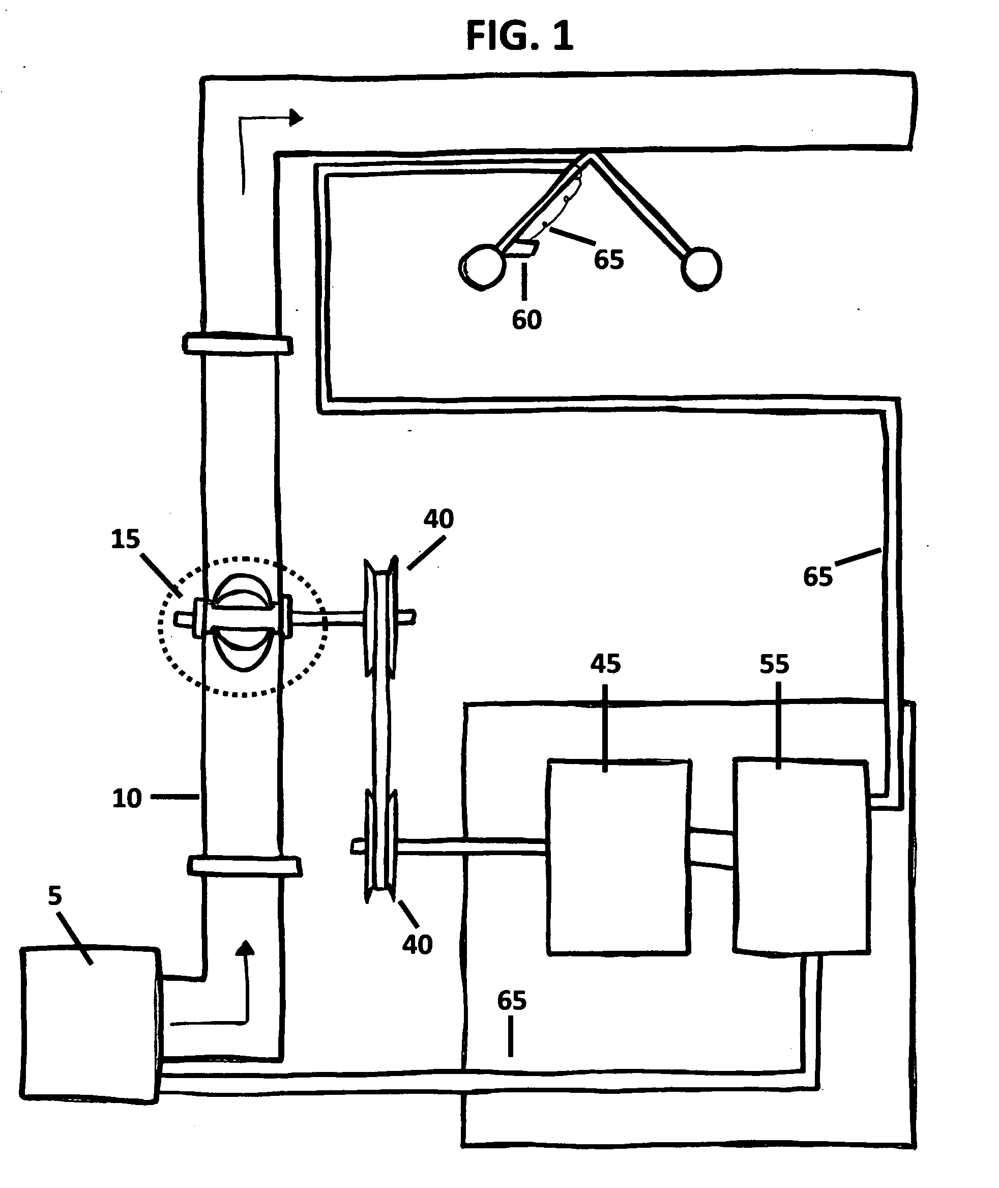
[0049]FIG. 1 shows the overall approach and design of the Kinetic Energy Recycling System. The system shown is comprised of an impeller assembly 15 connected to a shaft 25 which then by means of rotational energy transfer device 40 or other coupling arrangement transfers the rotational energy from the impeller assembly 15 to the generator for producing electrical power 45. The generated electrical energy from 45 is than conveyed by wires to the automatic transfer switch 55 which distributes this usable energy to the electric drive motors of the irrigation towers 60 and the electrical motor that powers the well 5. In the event the well is powered by fossil fuel, 55 would send electrical power to recharge the well motor batteries, not shown in FIG.

[0050]FIG. 2 shows the same overall approach and design of t...


PUM


Abstract

A process that allows the recycling of kinetic energy that is present through the motion of fluid and air transfer. This process shall utilize the use of an impeller assembly that will be introduced into the fluid or air stream of an agricultural or manufacturing process examples are but not limited to irrigation, fan exhaust and air circulation. The fluid or air passes over the impeller recycling the kinetic energy from the motion of this medium to into rotational energy. This rotational energy is conveyed to a generating unit that coverts the recycled energy into usable energy. This usable energy can then be sent back to the process that created it or transferred onto the public utility power grid. This process will be a means of recycling the energy that we use everyday to be used again with no hazard to the environment.

Description

BACKGROUND OF INVENTION[0001]1. Field of the Invention[0002]The present invention relates to the development of a means for capturing and the recycling of kinetic energy from already existing energy sources into usable energy as an alternate energy power supply for equipment or return to the public power grid.[0003]2. Background of the Invention Prior Art[0004]There are limitations with previous hydroelectric applications. The problem with dammed up streams and waterfalls is the cost and hindrance of location relative to the power generation facility. Srybnik, U.S. Pat. No. 7,605,490 date of issue Oct. 20, 2009 was developed to try and use the energy from lower pressure streams as described in. This unit uses a secondary pump to increase the pressure to the impeller which adds to the energy demand of the system. Sipp, U.S. Pat. No. 7, 602,076 date of issue Oct. 13, 2009 will have the concern of low or lost water flow during drought conditions with units that utilize streams and smal...

Claims


Application Information

Patent Timeline
IPC IPC(8): F03D9/00F03B13/00
CPCF03B13/00F03D1/04F03D9/002F05B2220/20F05B2220/602Y02E10/728F05B2240/9111Y02B10/50Y02E10/465Y02E10/725F05B2220/604F03D9/25Y02E10/74Y02E10/46Y02E10/72Y02P70/50F03D3/04
Inventor STILES, ROBERT A.
Owner STILES ROBERT A
Why Eureka
Eureka Blog
Learn More