Wireless Energy Transfer with Negative Index Material

Inactive Publication Date: 2011-06-09
MITSUBISHI ELECTRIC RES LAB INC
View PDF58 Cites 105 Cited by
  • Summary
  • Abstract
  • Description
  • Claims
  • Application Information

AI Technical Summary

Benefits of technology

[0012]Embodiments of the invention are based on the realization that evanescent wave coupling is enhanced by arranging one or m

Problems solved by technology

To optimize the energy, a distance between the source and the sink should be as small as possible, because

Method used


Image

  • Wireless Energy Transfer with Negative Index Material
  • Wireless Energy Transfer with Negative Index Material
  • Wireless Energy Transfer with Negative Index Material

Examples


Embodiment Construction

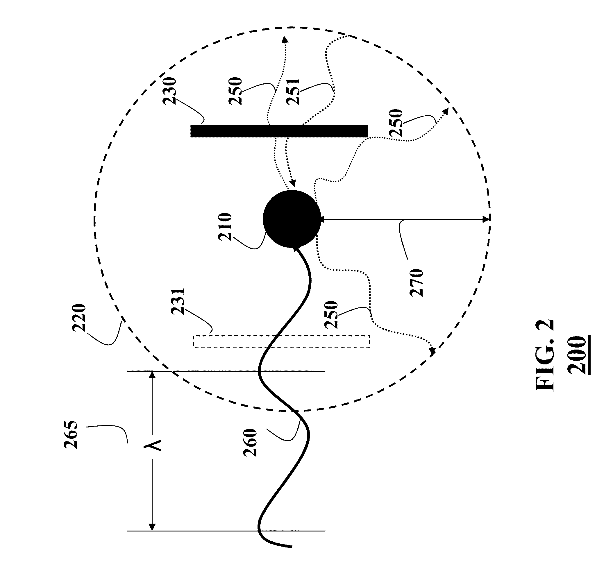
[0021]Embodiments of the invention are based on a realization that a negative index material (NIM) arranged in an electromagnetic (EM) near-field on a path of an evanescent wave while energy is transferred wirelessly, increases amplitude of the evanescent wave and, thus, optimizes the efficiency of the energy transfer.

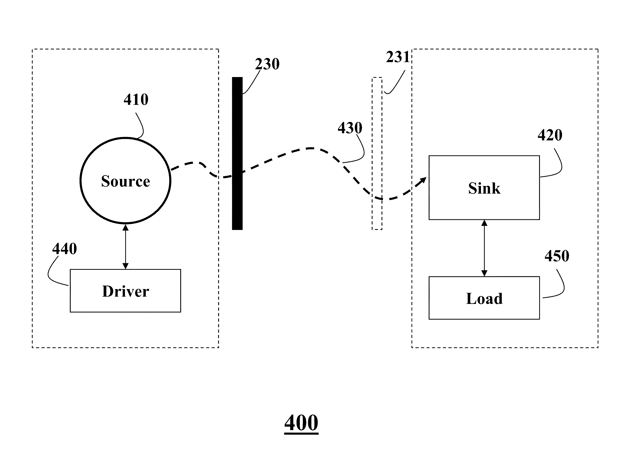
[0022]FIG. 2 shows a system 200 according an embodiment of the invention. The system is configured to exchange, e.g., transmit or receive, energy wirelessly and includes an electromagnetic (EM) non-radiative structure 210 configured to generate an electromagnetic near-field 220 when the energy is received by the structure and exchange the energy wirelessly via a coupling of evanescent waves.

[0023]In one embodiment, the energy 260 is supplied by a driver (not shown) as known in the art. In this embodiment, the structure 210 serves as a source of the wireless energy transfer system. In alternative embodiment, the energy 260 is supplied wirelessly from the source (not sho...


PUM


Abstract

Embodiments of the invention disclose a system configured to exchange energy wirelessly. The system includes a structure configured to exchange the energy wirelessly via a coupling of evanescent waves, wherein the structure is electromagnetic (EM) and non-radiative, and wherein the structure generates an EM near-field in response to receiving the energy; and a negative index material (NIM) arranged within the EM near-field such that the coupling is enhanced.

Description

RELATED APPLICATIONS[0001](MERL-2218) This application is related to U.S. patent application Ser. No. 12 / ______ entitled “Wireless Energy Transfer with Negative Index Material,” filed by Koon Hoo Teo et al. on Dec. 3, 2009, incorporated herein by reference. (MERL-2222) This application is related to U.S. patent application Ser. No. 12 / ______ entitled “Wireless Energy Transfer with Negative Index Material,” filed by Koon Hoo Teo et al. on Dec. 3, 2009, incorporated herein by reference. (MERL-2223) This application is related to U.S. patent application Ser. No. 12 / ______ entitled “Wireless Energy Transfer with Negative Index Material” filed by Koon Hoo Teo et al. on Dec. 3, 2009, incorporated herein by reference.FIELD OF THE INVENTION[0002]The present invention relates to transferring energy, and more particularly, to transferring energy wirelessly.BACKGROUND OF THE INVENTIONWireless Energy Transfer[0003]Inductive coupling is used in a number of wireless energy transfer applications s...

Claims


Application Information

Patent Timeline
IPC IPC(8): H02J17/00H01F38/00
CPCH02J17/00B66B7/00H02J50/12
Inventor TEO, KOON HOOHUANG, DAIYER, VISHWANATHWANG, BINGNAN
Owner MITSUBISHI ELECTRIC RES LAB INC
Why Eureka
Try Eureka