Rotating Electrical Machine

a technology of rotating electrical machines and rotating shafts, which is applied in the direction of electric devices, propulsion by batteries/cells, magnetic circuit shapes/forms/construction, etc., can solve the problems of not always ensuring smooth flow, and achieve the effect of improving cooling efficiency

Inactive Publication Date: 2011-06-09
HITACHI LTD
View PDF5 Cites 83 Cited by
  • Summary
  • Abstract
  • Description
  • Claims
  • Application Information

AI Technical Summary

Benefits of technology

[0017]According to the present invention, even when the rotating electrical machine is installed horizontally, the cooling medium can be distributed by taking advantage of the difference in height created by an inclination of the cooling medium paths and thus, the cooling efficiency can be improved.

Problems solved by technology

This means that the system disclosed in the above mentioned Japanese Laid Open Patent may not always assure a smooth flow of the cooling medium through the slot once the cooling medium is delivered into the slot.

Method used


Image

  • Rotating Electrical Machine
  • Rotating Electrical Machine
  • Rotating Electrical Machine

Examples


first embodiment

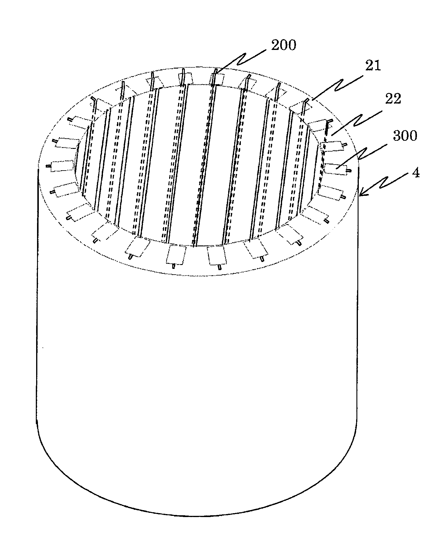
[0047]FIGS. 4 and 5 illustrate the rotating electrical machine achieved in the first embodiment of the present invention. FIG. 4 shows a perspective view of the stator core 4. FIG. 5A and FIG. 5B show the stator core 4 over an area around a slot 300, where FIG. 5A presenting a first example of a slot structure and FIG. 5B presenting a second example of a slot structure.

[0048]A plurality of slots 300 are formed on the inner side of the stator core 4 in its circumferential direction with equal intervals. In the embodiment, a groove 200, which serves as a cooling medium path, is formed at a wall surface of each slot 300. Such grooves 200 are each formed so as to go through from one end face of the stator core 4 to the other end face of the stator core 4. In addition, the slots 300, the teeth 22 and the grooves 200 all assume a twisted structure, i.e., a skew structure, so as to twist around the central axis of the stator core 4. While the stator core 4 is formed by laminating a plurali...

second embodiment

[0065]FIGS. 10A and 10B illustrate the second embodiment of the present invention. In the first embodiment described above, the skew structure of grooves 200 is, formed by twisting the entire laminated body constituting the stator core 4, and thus the grooves 200 are inclined relative to the central axis of the stator core 4. In contrast, the second embodiment is distinguishable from the first embodiment in that the slots 300, which houses the stator winding 5 and the teeth 22, extend parallel to the central axis of the stator core 4, and that only the grooves 200 are inclined relative to the central axis.

[0066]FIG. 10A shows a perspective view of a portion of the stator core 4, whereas FIG. 10B is a sectional view taken along D-D in the FIG. 10A. A groove 200 is formed on the bottom side of each slot 300 (on the wall surface located toward the yoke portion 21). It is to be noted that two or more grooves 200 may be formed. While the grooves 200 are formed in advance in each of the s...

third embodiment

[0069]FIGS. 11A, 11B, and 12 illustrate the third embodiment of the rotating electrical machine according to the present invention. FIG. 11A shows the front-side end face of the stator core 4, whereas FIG. 11B shows the rear-side end face of the stator core 4. FIG. 12 is a sectional view taken along E-E in FIG. 11A.

[0070]While a groove 200 is formed on the wall surface of each slot 300 in the first and second embodiments described above, through holes 211 to 216 serving as cooling medium paths, are formed in the stator core 4 in the third embodiment. In addition, slots 300 and teeth 22 are formed to extend parallel to the central axis of the stator core 4 without twisting, similar to the second embodiment.

[0071]As shown in FIGS. 11A and 11B, the through holes 211, 212 and 216 are formed so that the openings on the front-side end face (cooling medium inflow ports) are provided closer to the outer circumferential surface of the stator core 4, and the openings on the rear-side end face...


PUM


Abstract

A rotating electrical machine includes: a stator that includes a cylindrical stator core and a stator winding wire wound around the stator core; and a rotor disposed facing the stator via a gap; wherein at least one cooling medium path extending in a direction of a central axis of the stator core is provided in the stator; and the cooling medium path is inclined relative to the central axis of the stator core.

Description

INCORPORATION BY REFERENCE[0001]The disclosure of the following priority application is herein Incorporated by reference: Japanese Patent Application No. 2009-276571 filed Dec. 4, 2009.BACKGROUND OF THE INVENTION[0002]1. Field of the Invention[0003]The present invention relates to a rotating electrical machine with a stator cooled with a cooling medium.[0004]2. Description of Related Art[0005]The standard procedures through which a stator of a rotating electrical machine that drives an electric vehicle is cooled include an oil cooling method whereby an ATF (automatic transmission fluid) in the transmission is directly sprayed onto winding portions (coil end portions) exposed at ends located along the rotational axis of the rotating electrical machine.[0006]As an alternative to the method whereby the cooling medium is directly sprayed onto the winding, there is a method known in the related art whereby the stator is cooled with a cooling medium delivered into a slot (see, for instanc...

Claims


Application Information

Patent Timeline
Patent Type & Authority Applications(United States)
IPC IPC(8): H02K9/19
CPCH02K1/20Y02T10/641H02K9/19H02K3/24B60L3/0061B60L15/20B60L2220/14B60L2220/18B60L2240/36B60L2240/423B60L2270/142B60L2270/145B60L2270/147Y02T10/72B60L50/51Y02T10/64Y02T10/70H02K9/197
Inventor SUGIMOTO, SHINJIKOMURA, AKIYOSHIOBATA, KOJIISHIGAMI, TAKASHIKIKUCHI, SATOSHI
Owner HITACHI LTD
Why Eureka
Try Eureka