Rotating wheel electrode device for gas discharge sources comprising wheel cover for high power operation

a technology of electrode device and rotating wheel, which is applied in the direction of discharge tube main electrode, gas-filled discharge tube, incadescent cooling arrangement, etc., can solve the problems of liquid metal discharging heat and overheating of electrodes at higher power, and achieve the effect of high input power

Active Publication Date: 2011-06-09
USHIO DENKI KK
View PDF9 Cites 15 Cited by
  • Summary
  • Abstract
  • Description
  • Claims
  • Application Information

AI Technical Summary

Benefits of technology

[0004]It is an object of the present invention to provide an electrode device for use in a gas discharge source and a corresponding gas discharge source, which allow the operation of the gas discharge source with a high input power without overheating the electrode wheels.

Problems solved by technology

Furthermore, the liquid metal dissipates the heat introduced into the electrodes by the gas discharge.
With the above described known gas discharge source, the heat dissipation from electrode wheels is not sufficiently high which results in overheating of the electrodes at higher powers.

Method used


Image

  • Rotating wheel electrode device for gas discharge sources comprising wheel cover for high power operation
  • Rotating wheel electrode device for gas discharge sources comprising wheel cover for high power operation
  • Rotating wheel electrode device for gas discharge sources comprising wheel cover for high power operation

Examples


Embodiment Construction

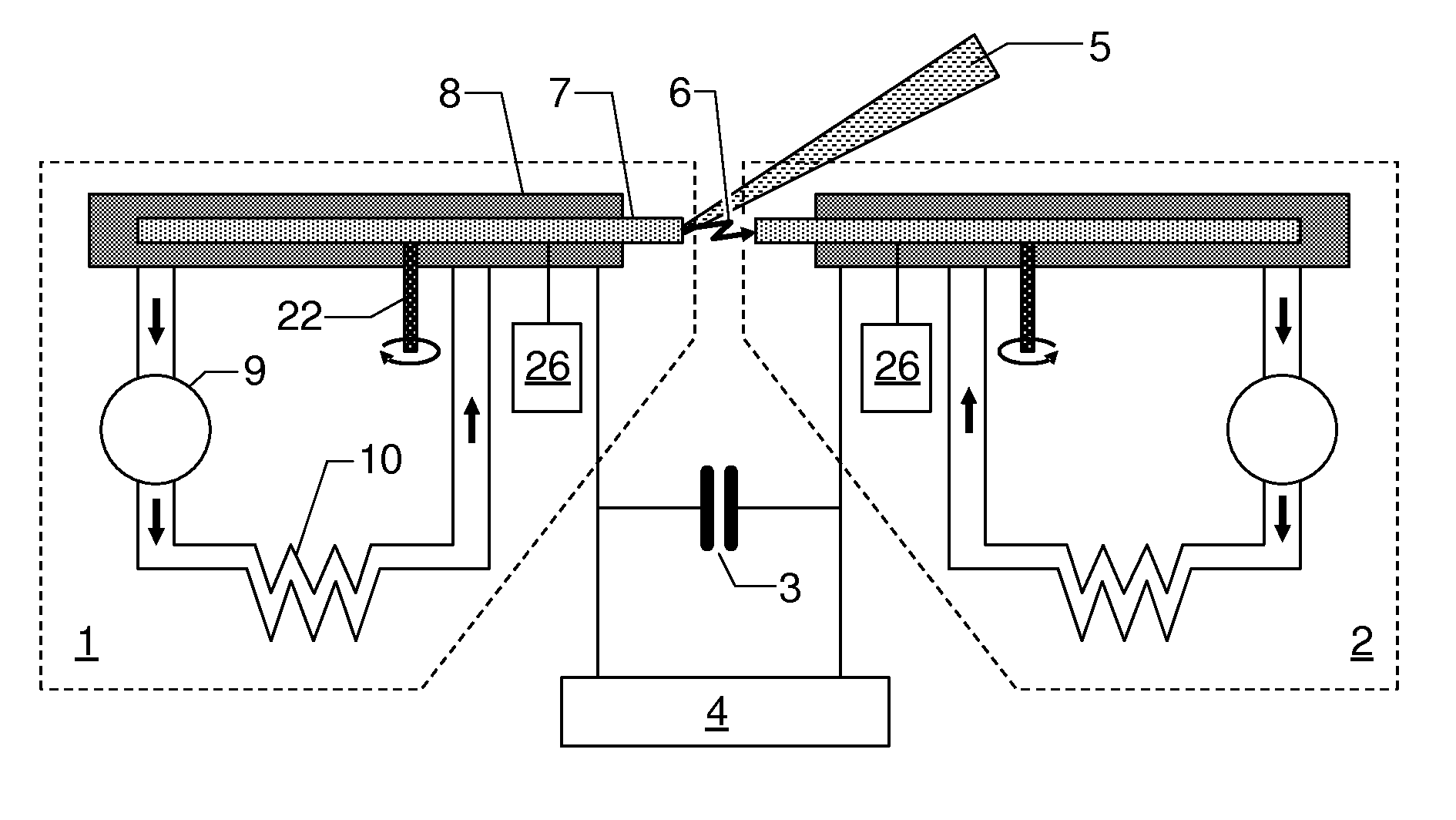
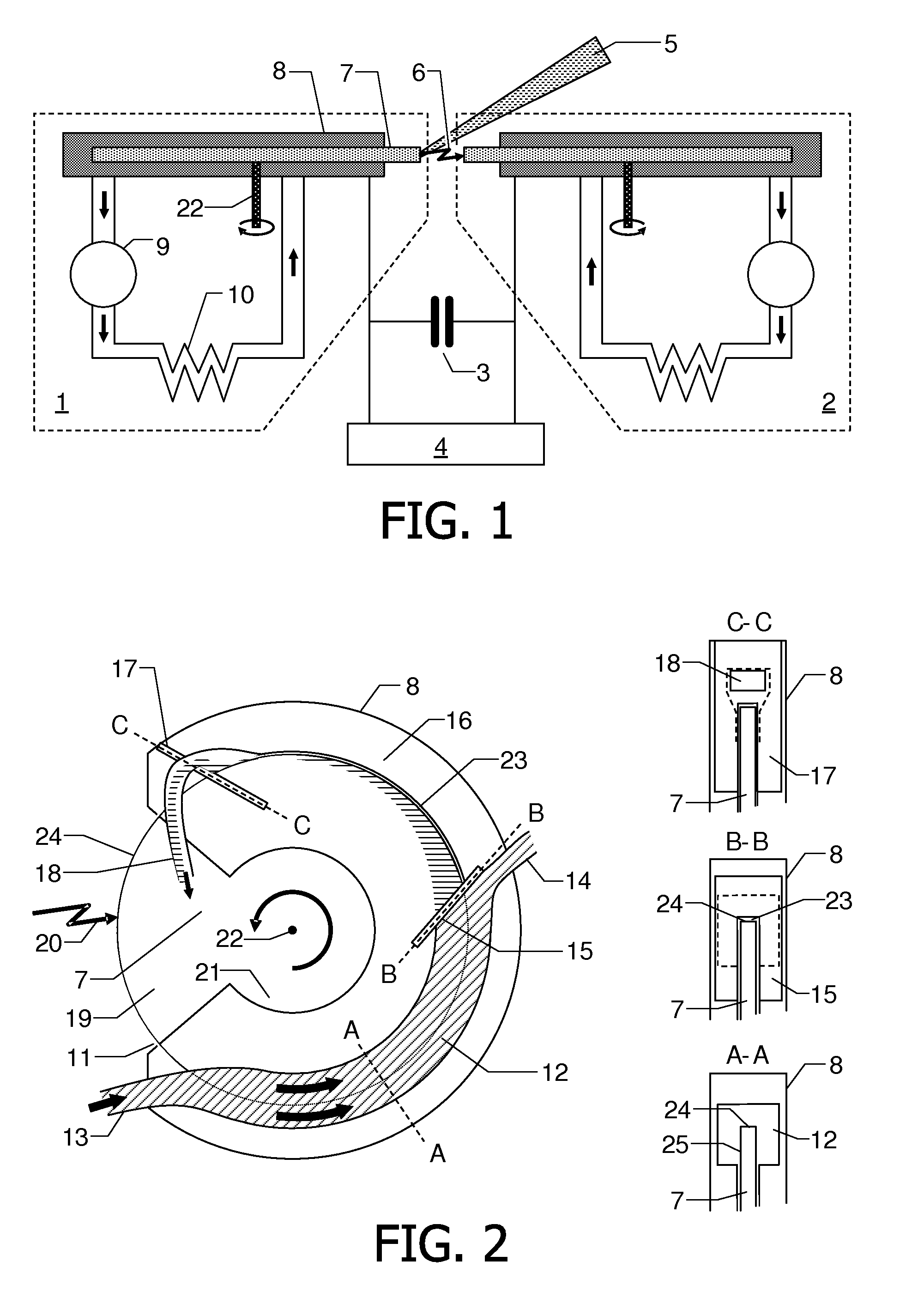
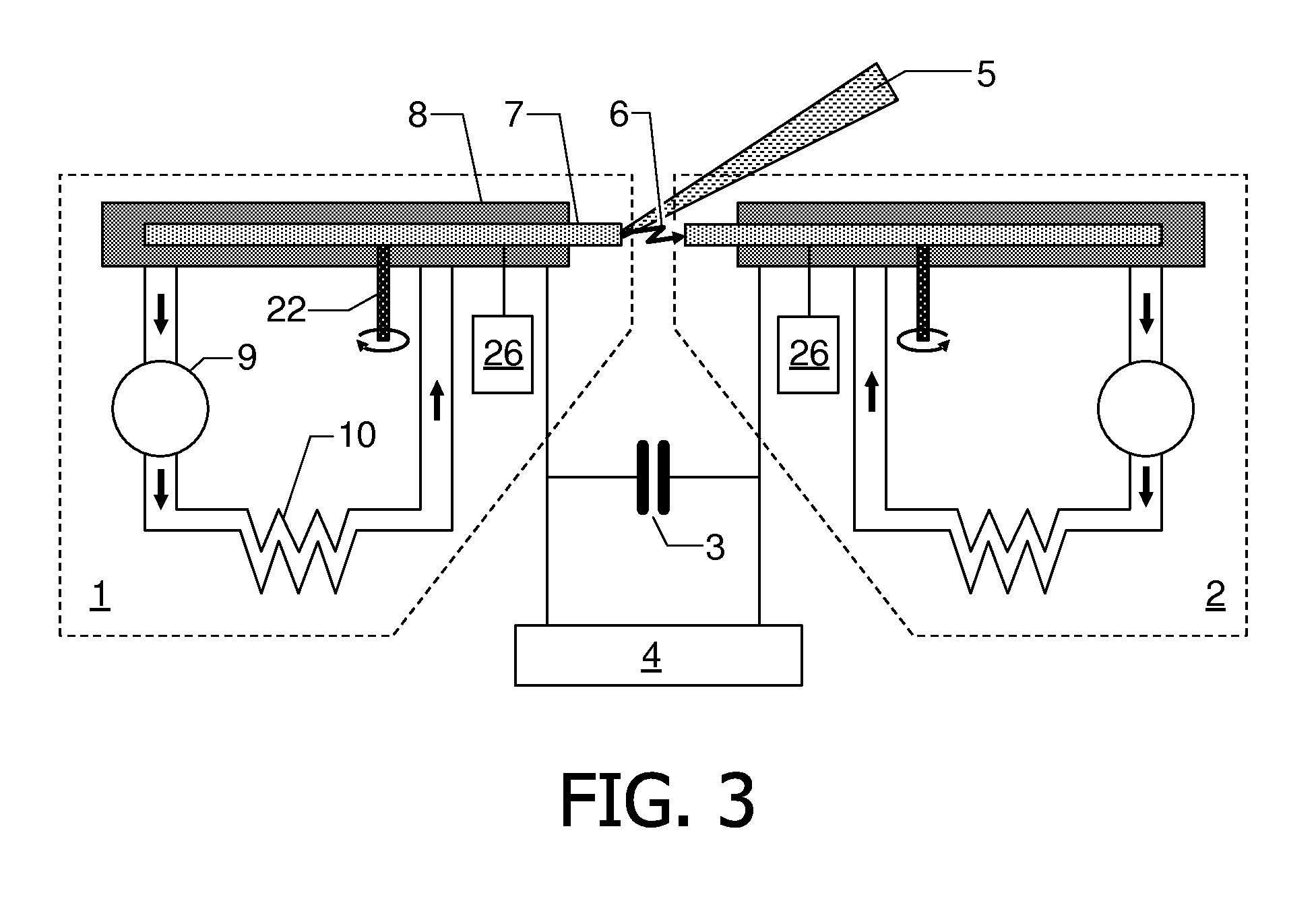
[0034]FIG. 1 shows a schematic view of an exemplary gas discharge source with two electrode devices 1, 2 according to the present invention. The electrode devices 1, 2 are characterized by a specially designed encapsulation or cover 8 of the rotating electrode wheels 7 and a forced flow of liquid metal used in this gas discharge source for generation of a gas discharge.

[0035]The improved gas discharge source consists of the two rotating electrode devices 1, 2, which are connected to a capacitor bank 3 charged by a power supply 4. During operation of the gas discharge source, liquid metal is applied to the outer circumferential surface of the electrode wheels 7 to form a thin liquid metal film on this surface at the discharge location 6. An energy beam 5, for example a laser beam, is directed to the outer circumferential surface of one of the rotating electrode wheels 7 to evaporate part of the liquid metal at the discharge location 6 and to induce an electrical discharge between the...


PUM


Abstract

The present invention relates to an electrode device (1, 2) for gas discharge sources and to a gas discharge source having one or two of said electrode devices (1, 2). The electrode device (1, 2) comprises an electrode wheel (7) rotatable in a rotational direction around a rotational axis (22), said electrode wheel (7) having an outer circumferential surface (24) between two side surfaces (25). An electrode wheel cover (8) is provided which covers a portion of the outer circumferential surface (24) and the side surfaces (25) of the electrode wheel (24). The cover (8) is designed to form a cooling channel (12) in the circumferential direction between the cover (8), the outer circumferential surface (24) and radially outer portions part of the side surfaces (25), and to form a gap (23) between the cover (8) and the outer circumferential surface (24) in extension of the cooling channel (12) in the circumferential direction. The gap (23) has a smaller flow cross section than the cooling channel (12) and limits a thickness of the liquid material film formed on the outer circumferential surface (24) during rotation of the electrode wheel (7). Alternatively to the gap (23) the cover (8) may be designed to inhibit the formation of such a film from the liquid material flowing through the cooling channel (12). The cooling channel (12) allows at the same time cooling of the electrode wheel (7) by the liquid material circulating through the cooling channel (12). With the proposed design of the cover (8), an efficient cooling of the electrode wheel (7) is achieved, allowing high electrical powers for operating gas discharge sources with such an electrode device.

Description

FIELD OF THE INVENTION[0001]The present invention relates to an electrode device for gas discharge sources comprising at least one electrode wheel rotatable around a rotational axis, said electrode wheel having an outer circumferential surface between two side surfaces. The invention further relates to a gas discharge source comprising such an electrode device and to a method of operating the gas discharge source with this electrode device.BACKGROUND OF THE INVENTION[0002]Gas discharge sources are used, for example, as light sources for EUV radiation (EUV: extreme ultra violet) or soft x-rays. Radiation sources emitting EUV radiation and / or soft x-rays are in particular required in the field of EUV lithography. The radiation is emitted from hot plasma produced by a pulsed current. Known powerful EUV radiation sources are operated with metal vapor to generate the required plasma. An example of such a EUV radiation source is shown in WO 2006 / 123270 A2. In this known radiation source t...

Claims


Application Information

Patent Timeline
Patent Type & Authority Applications(United States)
IPC IPC(8): H01J61/52
CPCH05G2/003H01J1/88H05G2/005
Inventor ZHOKHAVETS, VLADZIMIRKRUECKEN, THOMASDERRA, GUENTHER HANS
Owner USHIO DENKI KK
Why Eureka
Try Eureka