
Despeckling Apparatus and Method

a technology of despeckling apparatus and spectrometer, which is applied in the direction of instruments, non-linear optics, optical elements, etc., can solve the problem that the coherence of laser light tends to produce undesirable speckles in the viewed image, and achieve the effect of reducing the speckles of light outpu

Active Publication Date: 2011-06-09
PROJECTION VENTURES INC
View PDF15 Cites 22 Cited by
  • Summary
  • Abstract
  • Description
  • Claims
  • Application Information

AI Technical Summary

Benefits of technology

[0003]In general, in one aspect, an optical apparatus where stimulated Raman scattering in an optical fiber reduces the speckle of the light output from the optical fiber.
[0004]Implementations may include one or more of the following features. The optical fiber core diameter and length may be selected to achieve a desired amount of reduction in speckle. The optical fiber may be a multimode fiber. The core diameter and length may be selected to achieve a desired color of light output. The desired color may be a primary color. The primary color may be green. There may be an optical parametric amplifier that generates blue and red. A portion of the stimulated Raman scattering may be red. There may be a red light source that is combined with the red stimulated Raman scattering light. A portion of the stimulated Raman scattering may be yellow and may be used to form a projected digital image with four primary colors. The green light output may have a color chromaticity of u′=0.099+ / −0.01 and v′=0.578+ / −0.01. There may be a laser light source and a digital projector. The laser light source may illuminate the optical fiber, and the optical fiber may illuminate the digital projector. The laser light source may include a pulsed laser and a second harmonic generator. The laser light source may have an output at 523.5 nm, 515 nm, or 532 nm. There may be a light coupling system and a homogenizing device. The laser light source may illuminate the light coupling system, the light coupling system may illuminate the optical fiber, the optical fiber may illuminate the homogenizing device, and the homogenizing device may illuminate the digital projector. There may be a second optical fiber and a variable light splitter. The variable light splitter may illuminate the first optical fiber and the second optical fiber, and stimulated Raman scattering in the second optical fiber may reduce speckle from the second optical fiber. The variable light splitter may include a rotating waveplate and a polarizing beam splitter. The second optical fiber may have a core diameter and length selected to achieve a desired amount of reduction in speckle. The laser light source may illuminate the variable light splitter, and the first optical fiber and the second optical fiber may illuminate the digital projector. The variable light splitter may be adjusted to achieve the desired color for a combined light output of the first optical fiber and the second optical fiber.

Problems solved by technology

There are many advantages for using laser light sources to illuminate digital projection systems, but the high coherence of laser light tends to produce undesirable speckle in the viewed image.

Method used


Image

  • Despeckling Apparatus and Method
  • Despeckling Apparatus and Method
  • Despeckling Apparatus and Method

Examples


Embodiment Construction

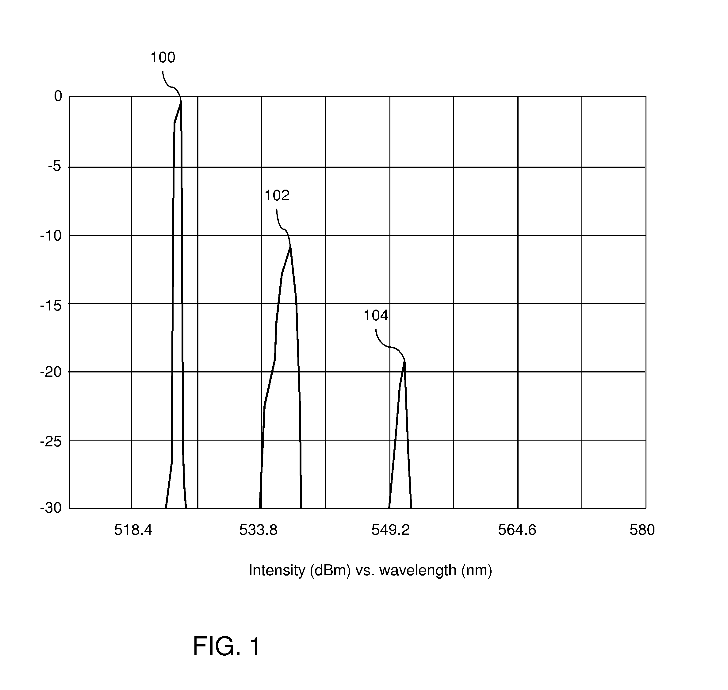
[0022]Raman gas cells using stimulated Raman scattering (SRS) have been used to despeckle light for the projection of images as described in U.S. Pat. No. 5,274,494. SRS is a non-linear optical effect where photons are scattered by molecules to become lower frequency photons. A thorough explanation of SRS is found in Nonlinear Fiber Optics by Govind Agrawal, Academic Press, Third Edition, pages 298-354. FIG. 1 shows a graph of stimulated Raman scattering output from an optical fiber at a moderate power which is only slightly above the threshold to produce SRS. The x-axis represents wavelength in nanometers (nm) and the y-axis represents intensity on a logarithmic scale in dBm normalized to the highest peak. First peak 100 at 523.5 nm is light which is not Raman scattered. The spectral bandwidth of first peak 100 is approximately 0.1 nm although the resolution of the spectral measurement is 1 nm, so the width of first peak 100 cannot be resolved in FIG. 1. Second peak 102 at 536.5 nm...


PUM

PropertyMeasurementUnit
FWHMaaaaaaaaaa
lengthaaaaaaaaaa
lengthaaaaaaaaaa

Abstract

An apparatus and method that reduces laser speckle by using stimulated Raman scattering in an optical fiber. The fiber core diameter and length are selected to achieve a desired output color. An adjustable despeckler is formed by combining two optical fibers in parallel and adjusting the amount of light in each path.

Description

RELATED APPLICATIONS[0001]The present application claims priority under 35 U.S.C. §119(e) to U.S. provisional patent application, U.S. Ser. No. 61 / 267429, filed Dec. 7, 2009, which is incorporated herein by reference.BACKGROUND OF THE INVENTION[0002]There are many advantages for using laser light sources to illuminate digital projection systems, but the high coherence of laser light tends to produce undesirable speckle in the viewed image. Known despeckling methods generally fall into the categories of polarization diversity, angle diversion, and wavelength diversity. In the laser projection industry, there has been a long-felt need for more effective despeckling methods.SUMMARY OF THE INVENTION[0003]In general, in one aspect, an optical apparatus where stimulated Raman scattering in an optical fiber reduces the speckle of the light output from the optical fiber.[0004]Implementations may include one or more of the following features. The optical fiber core diameter and length may be...

Claims


Application Information

Patent Timeline
Patent Type & Authority Applications(United States)
IPC IPC(8): G02F1/37G02F1/35H01S3/30
CPCG02B27/48H01S3/005H01S3/2383H01S3/302H01S3/30H04N9/3161H04N9/3197G02F1/35G02F1/37H01S2301/02
Inventor LIPPEY, BARRETBECK, WILLIAMTURNER, IAN
Owner PROJECTION VENTURES INC
Learn More