Integrated Collimator

Active Publication Date: 2011-06-09
MOXTEK INC
View PDF2 Cites 1 Cited by
  • Summary
  • Abstract
  • Description
  • Claims
  • Application Information

AI Technical Summary

Benefits of technology

[0011]It has been recognized that it would be advantageous to create a collimator for a radiation detector that has an opening with a width that is substantially the same as the anode in order to optimize the collection of x-rays directed towards the full-charge collection region while also blocking x-rays directed towards the partial-charge collection region. It has also been recognized that it would be advantageous to create a collimator that can be precisely aligned over the anode. It has also been recognized that it would be advantageous to create a collimator with the advantages of both high atomic number materials and low atomic number materials.

Problems solved by technology

Signals that are reduced because of the loss of charge carriers to recombination or to the guard ring contribute to “background” and interfere with the determination of the type of material that produced the x-rays.
Having a width w1, dimension or area of the collimator opening 15 that is less than the width w2, dimension or area of the anode can result in some undesirable blocking of x-rays.
Such undesirable blocking of x-rays can result in an undesirable longer collection time required for determination of the x-ray signal strength and thus the type of material that produced the x-ray.
Such collimator alignment can be a difficult manufacturing challenge and can frequently result in misalignment.
Thus misalignment of the collimator can result in the undesirable results of x-rays impinging on the partial-charge collection region 16 and or blocking of x-rays that would otherwise impinge on the full-charge collection region 17.
A disadvantage of the use of high atomic number collimator materials, however, is that x-rays emitted from the high atomic number collimator material can be similar in energy to the x-rays being measured, that were emitted from a sample material.
Because of this similarity in x-ray energy between x-rays emitted from the sample material and x-rays emitted from the collimator, x-rays emitted from the collimator can interfere with determination of the type or quantity of material that is being analyzed.
In contrast, a collimator material with a low atomic number can result in emission of x-rays that are so low in energy that there is little effect on detector performance.
A problem of low atomic number collimator materials is that they can be less effective at blocking high energy x-rays emitted from the sample.

Method used


Image

  • Integrated Collimator
  • Integrated Collimator
  • Integrated Collimator

Examples


Embodiment Construction

[0020]Reference will now be made to the exemplary embodiments illustrated in the drawings, and specific language will be used herein to describe the same. It will nevertheless be understood that no limitation of the scope of the invention is thereby intended. Alterations and further modifications of the inventive features illustrated herein, and additional applications of the principles of the inventions as illustrated herein, which would occur to one skilled in the relevant art and having possession of this disclosure, are to be considered within the scope of the invention.

[0021]The term “x-rays” can include radiation of frequencies other than x-rays. The term “x-rays” is used in place of radiation because the invention described is typically used for sensing x-rays. It will be appreciated that this invention can be used for radiation other than x-rays.

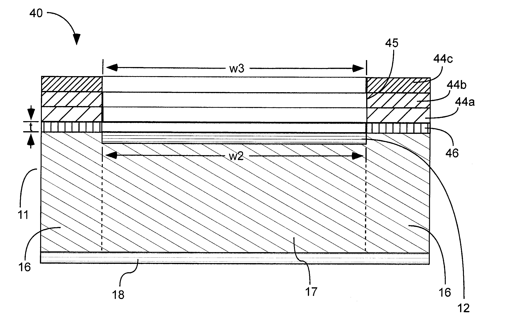
[0022]As illustrated in FIGS. 4-5, a radiation detector 40 with an integrated collimator 44 is shown. The radiation detector can in...


PUM


Abstract

A radiation detector with an integrated collimator. The collimator may be deposited on an anode or cathode face of the radiation detector. An insulating material may be deposited between the collimator and the radiation detector if the collimator is deposited on the anode side. The collimator may be comprised of a single layer or of multiple layers. Patterning and etching may be used to create an aperture in the collimator to allow x-rays to impinge on a full charge collection region of the radiation detector intrinsic region.

Description

FIELD OF THE INVENTION[0001]The present invention relates to radiation detectors.BACKGROUND[0002]A radiation detector 10 can include an intrinsic region 11, an anode 12, and a cathode 18 as shown in FIGS. 1 and 2. Radiation detectors can include other components not shown, such as a guard ring. The anode 12 can be disposed at one face of the radiation detector, called an “anode face”. The cathode 18 can be disposed at the opposite face of the radiation detector, called a “cathode face”. The term “face” may be used in referring to either the “anode face” or the “cathode face”.[0003]Radiation, such as x-rays, impinging upon the radiation detector can be absorbed by the detector. Each x-ray photon that is absorbed can create charge carriers, comprised of electron—hole pairs. Due to a potential difference between the anode and the cathode, positive charge carriers (holes) can be drawn to the anode and negative charge carriers (electrons) can be drawn to the cathode. The number of charge...

Claims


Application Information

Patent Timeline
IPC IPC(8): G21K1/02G01T1/00G01T1/29B44C1/22
CPCG21K1/02G01T1/24
Inventor DECKER, KEITH
Owner MOXTEK INC
Why Eureka
Try Eureka