
Apparatus and method for controlling operation of electric oil pump

a technology of electric oil pump and electric motor, which is applied in mechanical apparatus, machines/engines, positive displacement liquid engines, etc., can solve the problems of difficult to accurately reflect the actual state of oil to and inability to accurately predict the actual load torque, etc., to accurately control the operation of the pump and accurately reflect the viscosity characteristics of oil.

Active Publication Date: 2011-06-09
HYUNDAI MOTOR CO LTD +1
View PDF1 Cites 42 Cited by
  • Summary
  • Abstract
  • Description
  • Claims
  • Application Information

AI Technical Summary

Benefits of technology

The present invention provides an apparatus and method for controlling the operation of an electric oil pump by accurately reflecting the viscosity characteristics of oil, instead of measuring the temperature of the oil to reflect the state of the oil. This allows for more precise control of the pump's operation. The apparatus includes a current detector, a rotational speed detector, and a controller that calculates a load torque of the motor and targets a specific rotational speed for optimal pump operation. The invention can be used in various vehicles, including hybrid vehicles, electric vehicles, and other alternative fuel vehicles.

Problems solved by technology

However, the viscosity characteristics of the oil are changed as the use of the transmission continues, which are different from those of a new product, and thus it is impossible to accurately predict the actual load torque.
Preferably, in the case where the oil temperature is measured to reflect the oil viscosity during the control of the rotational speed of the motor in the conventional manner, a temperature-rotational speed map reflecting the initial conditions of new oil is used as it is, and thus after the elapse of a predetermined time, it can be difficult to accurately reflect the actual state of the oil to control the operation of the pump.

Method used


Image

  • Apparatus and method for controlling operation of electric oil pump
  • Apparatus and method for controlling operation of electric oil pump
  • Apparatus and method for controlling operation of electric oil pump

Examples


Embodiment Construction

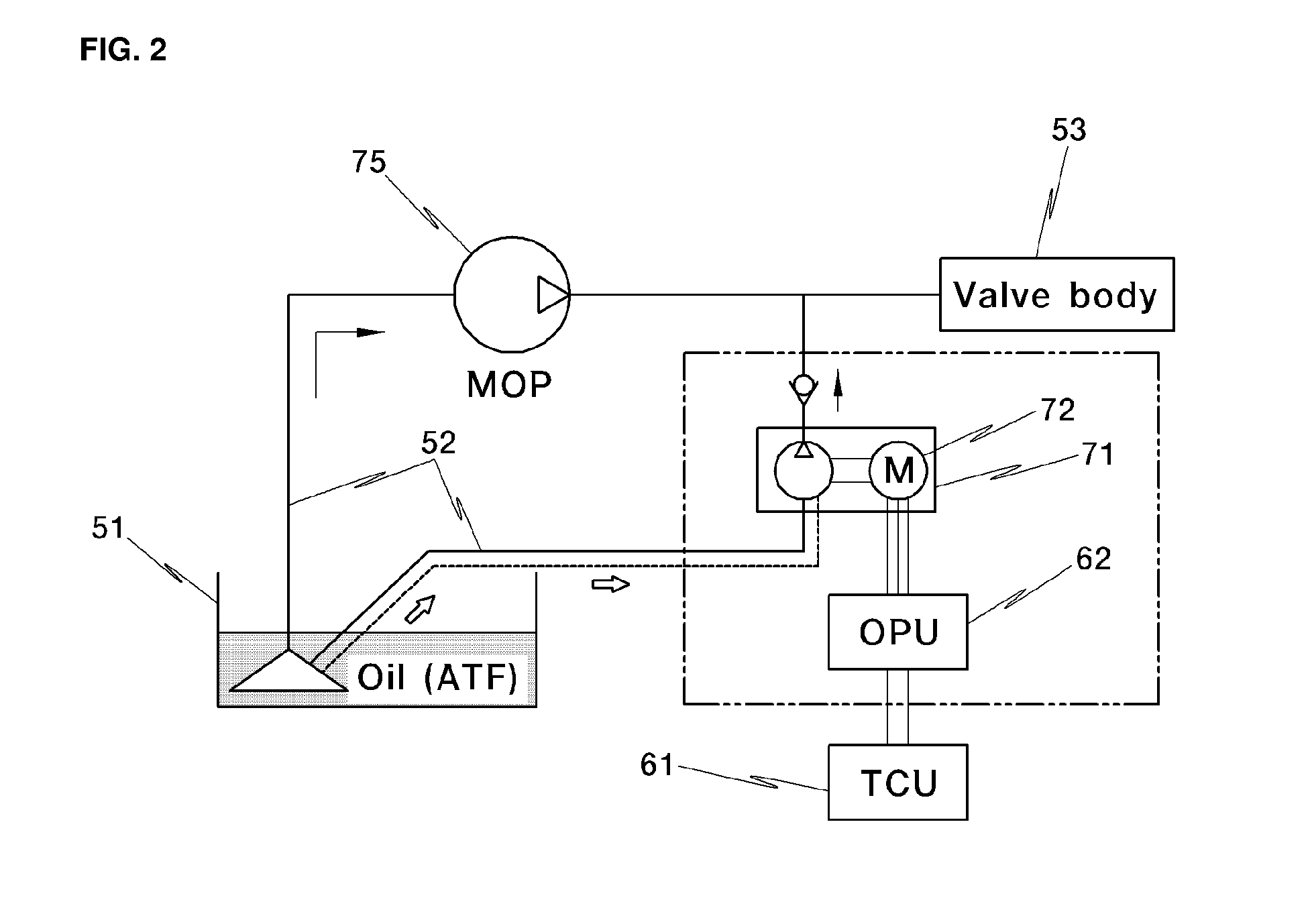
[0041]According to one preferred aspect, the present invention features a method for controlling the operation of an electric oil pump, the method comprising detecting a current applied to a motor of an electric oil pump, detecting a rotational speed of the motor, calculating a load torque of the motor based on the current and the rotational speed, calculating a target rotational speed based on the current and the rotational speed, and controlling the operation of the motor of the pump based on the calculated target rotational speed.

[0042]In one embodiment, the current applied to a motor of an electric oil pump is detected at a current detector.

[0043]In another embodiment, the rotational speed of the motor is detected with a rotational speed detector.

[0044]In another further preferred embodiments, the load torque of the motor is calculated based on the current and the rotational speed detected by the current detector and the rotational speed detector.

[0045]Hereinafter reference will...


PUM


Abstract

The present invention provides an apparatus and method for controlling the operation of an electric oil pump for creating a working fluid pressure in a transmission and a clutch for a hybrid vehicle, which can accurately reflect the viscosity characteristics of oil to accurately control the operation of the pump, instead of measuring the temperature of the oil to reflect the state of the oil. In preferred embodiments, the present invention provides an apparatus for controlling the operation of an electric oil pump, the apparatus including: a current detector for detecting a current applied to a motor of an electric oil pump; a rotational speed detector for detecting a rotational speed of the motor; and a controller for calculating a load torque of the motor based on the detection values of the current detector and the rotational speed detector, calculating a target rotational speed based on the detection values, and controlling the operation of the motor based on the target rotational speed.

Description

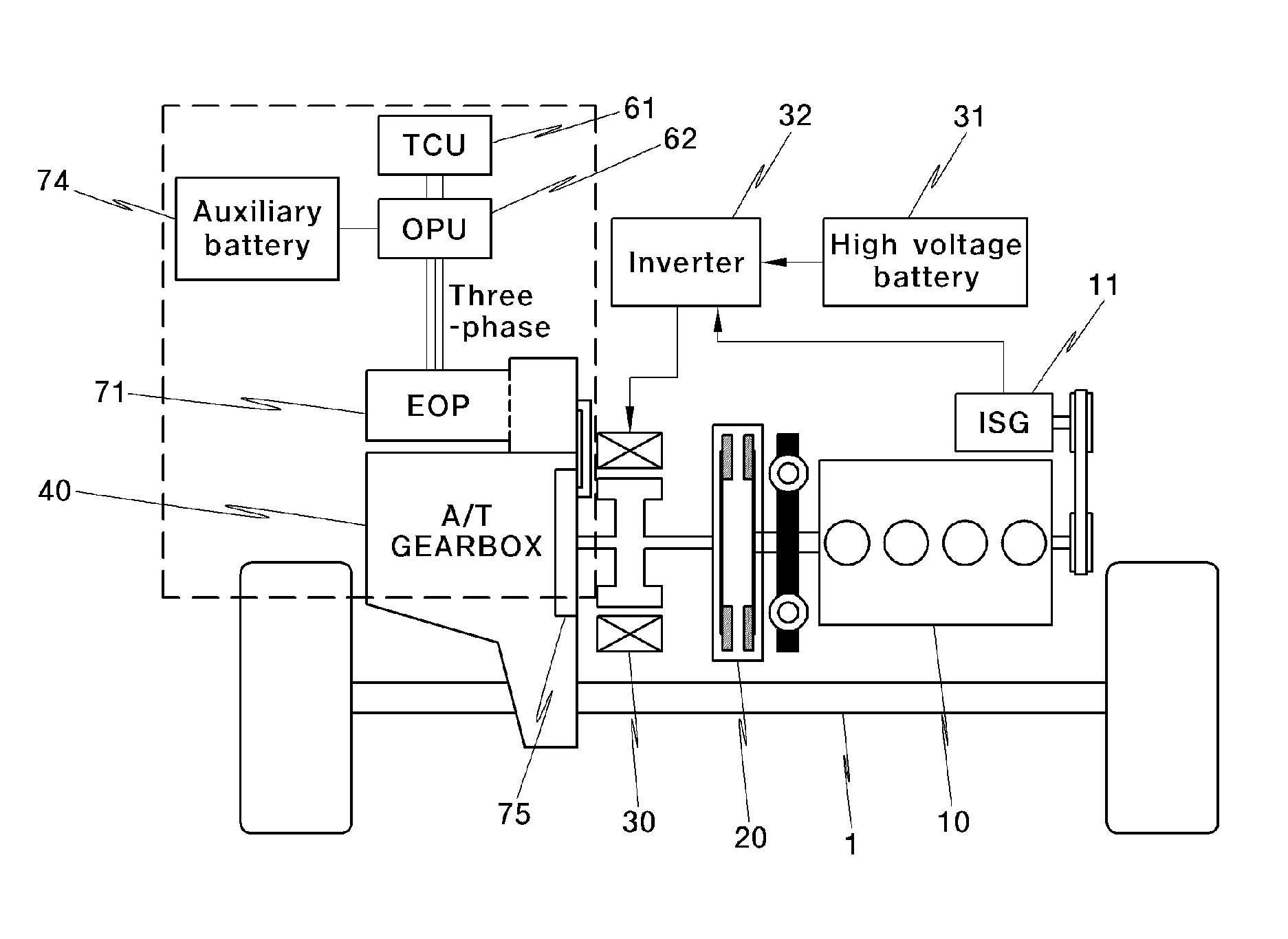
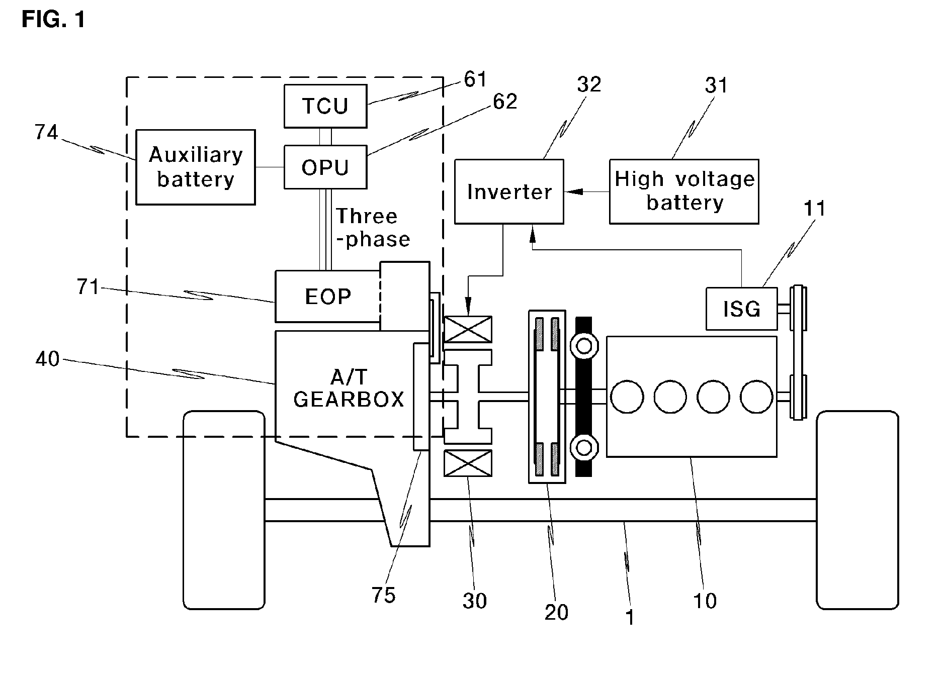
CROSS-REFERENCE TO RELATED APPLICATION[0001]This application claims under 35 U.S.C. §119(a) the benefit of Korean Patent Application No. 10-2009-0119793 filed Dec. 4, 2009, the entire contents of which are incorporated herein by reference.BACKGROUND[0002](a) Technical Field[0003]The present disclosure relates, generally, to an electric oil pump. More particularly, it relates to an apparatus and method for controlling the operation of an electric oil pump for creating a working fluid pressure in a transmission and a clutch for a hybrid vehicle.(b) Background Art[0004]Hybrid vehicles are the vehicles of the future that employ a motor as an auxiliary power source as well as a gasoline engine to provide a reduction in exhaust gas and an improvement in fuel efficiency. As shown in FIG. 1, a typical hybrid vehicle includes an engine 10 and a drive motor 30 as power sources for running the vehicle, an engine clutch 20 for connecting the engine 10 and the drive motor 30, an integrated-start...

Claims


Application Information

Patent Timeline
Patent Type & Authority Applications(United States)
IPC IPC(8): F04B49/06
CPCF04B2203/0209F04B49/06F16H61/0031F01M1/02F16N13/06F04D13/06F02D29/02
Inventor LEE, HAK SUNGKONG, SEUNG KILEE, JIN SOOKYI, JAE SHINKIM, YEON HOKIM, BAEK YUJEONG, SANG HYUNKIM, JONG HYUN
Owner HYUNDAI MOTOR CO LTD
Learn More