
Core material for sandwich panel, method of molding core material for sandwich panel, sandwich panel, and method of molding sandwich panel

a sandwich panel and core material technology, applied in the field of core material for sandwich panels, can solve the problems of small limitation of the shape of the molded product, the inability to achieve sufficient flexural rigidity as an entire sandwich panel, and the difficulty of forming a molded product including a sealed hollow portion inside only by injection molding

Active Publication Date: 2011-06-09
KYORAKU CO LTD
View PDF12 Cites 44 Cited by
  • Summary
  • Abstract
  • Description
  • Claims
  • Application Information

AI Technical Summary

Benefits of technology

In view of the above technical problems, another object of the present invention is to provide a method of forming a sandwich panel which is capable of realizing the sandwich panel with a sufficient strength, any profile or pattern without a need to reheat elements of the sandwich such as skin sheets, the core member, etc.
According to the method of forming the sandwich panel of the present invention, skin sheets sandwiching the core member can be formed on the spot by utilizing the thermo plastic sheet-like parison in a molten state, while its characteristics in which it is formed along the cavity of the mold can be prevented from being deteriorated due to the reheating of the skin sheet from outside, while at the same time, the adhesive strength of the outer peripheral parting line constituting a welding portion of the skin sheets, or the adhesive strength between the skin sheet and the core member can be prevented from being deteriorated, whereby the sandwich panel with a sufficient strength and any profile or surface shape can be provided without a need to reheat the skin sheet.

Problems solved by technology

According to the method of forming the resin sandwich panel by such an injection molding, it is feasible to form not only a molded product with a constant cross section, but also that with any profile whose cross section varies, so that there is a small limitation to the shape of the molded product, as compared with the extrusion molding.
However, since, in the injection molding, resin in a molten state is injected into a sealed mold space to be pressed against an inner surface of the sealed mold to be formed, it is technically difficult to form a molded product including a sealed hollow portion inside only by injection molding.
However, a sufficient flexural rigidity as an entire sandwich panel cannot be attained, since adhesion properties between the pair of plates constituting the core member are poor.
More specifically, a pair of resin plates are caused to pass between rollers including the stepped roller to be adhered to each other by a pressing force being applied thereto, so that sufficient adhesion properties are not obtained due to the fact that the adhesion between the pair of resin plates is not a surface-to-surface adhesion, but close to a point-to-point adhesion and that the time period for adhering the pair of plates is short.
The following technical problems can be caused due to such a reheating.
Firstly, in the sandwich panel formed by the sheet forming process, it is difficult to attain a complicated outer shape and a complicated pattern on its surface.
More specifically, it is difficult to bring the inside of the sheet into a sufficient molten state by such a reheating which heats the sheet from its outer surface.
If the time period for heating the sheet is lengthened in order to make the inside of the sheet the sufficient molten state, the sheet is caused to sag on its own weight, which makes the forming process itself difficult.
Even if the sheet is formed, it is not technically feasible to attain the complicated outer shape or the emboss pattern, etc. on its surface, since a characteristics in which the sheet is formed along the cavity of the mold becomes worse.
Secondly, in the sandwich panel formed by the sheet forming process, it is difficult to obtain the sandwich panel with a sufficient strength in a case where it is used as a structural member.
More specifically, since the welding strength of an outer peripheral parting line PL which is a welded portion between the skin sheets, or the welding strength of a welded portion between the skin sheet and the core member becomes worse due to a bad influence of the above-described reheating on the molding properties, the strength of the entire sandwich panel becomes deteriorated.
However, if the sandwich panel is formed by the blow molding or the vacuum forming, a peculiar technical problem associated with a blow-up ratio is caused.
However, on the other hand, the larger the thickness of the core member becomes, the bigger the blow-up ratio becomes, so that a phenomenon in which a peripheral edge portion of an opening of each of the plurality of dents on the core member becomes dull, whereby a flatness is so lowered that the adhesion area on the surface of the core member is substantially lost, and as a result, it becomes difficult to secure the sufficient adhesion properties between the core member and the skin sheets.
Even if the thickness of the core member is secured and the sufficient adhesion properties between the core member and the skin sheet are maintained, the core member itself can be destroyed or fractured.

Method used


Image

  • Core material for sandwich panel, method of molding core material for sandwich panel, sandwich panel, and method of molding sandwich panel
  • Core material for sandwich panel, method of molding core material for sandwich panel, sandwich panel, and method of molding sandwich panel
  • Core material for sandwich panel, method of molding core material for sandwich panel, sandwich panel, and method of molding sandwich panel

Examples


Embodiment Construction

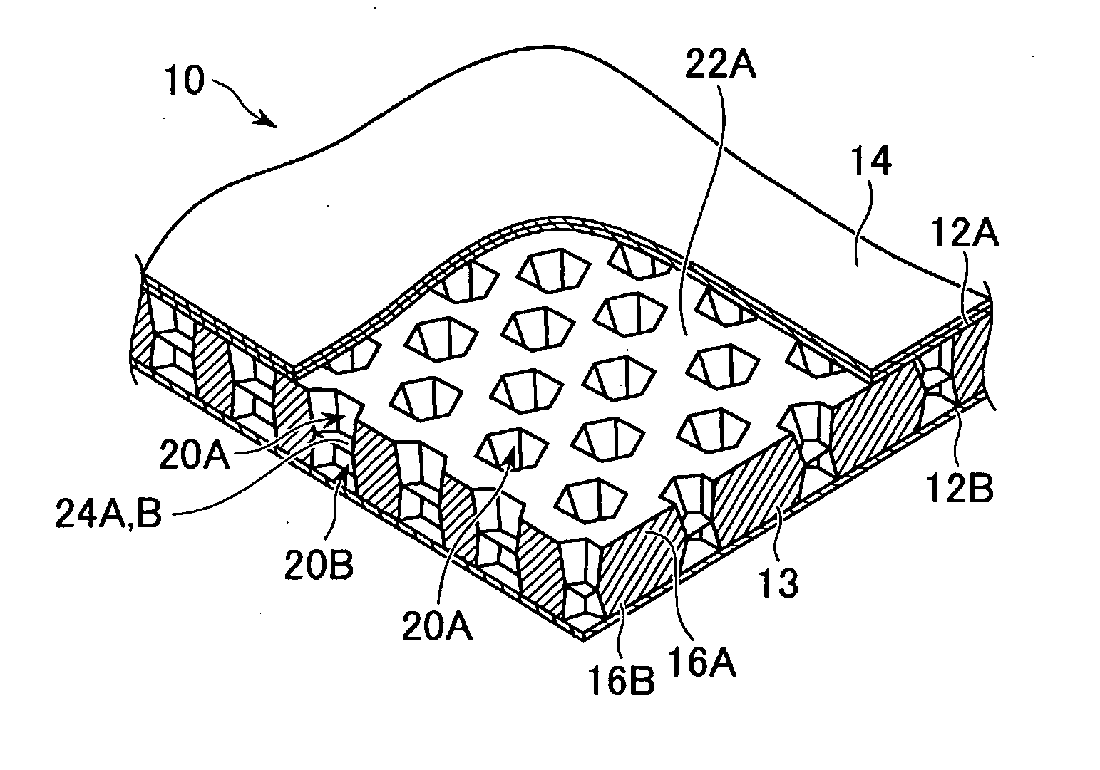
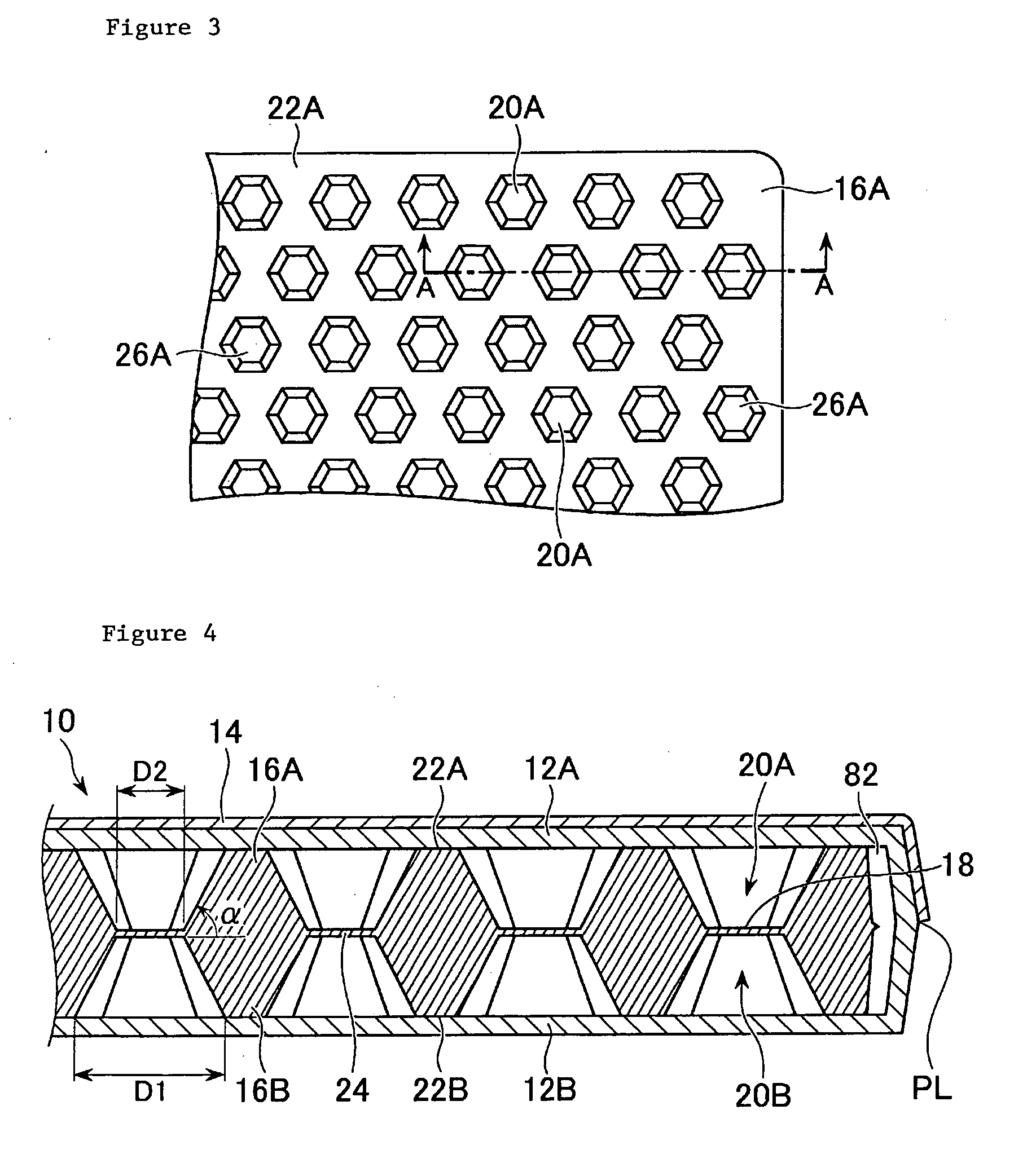
Embodiments of the core member made of a thermoplastic resin for a sandwich panel, the method of forming such a core member, the sandwich panel including such a core member, and the method of forming the sandwich panel according to the present invention will be explained in detail with reference to the drawings. The following embodiments are based on a case where the sandwich panel is used for a cargo floor lid for an automobile which requires a light weight and a high stiffness.

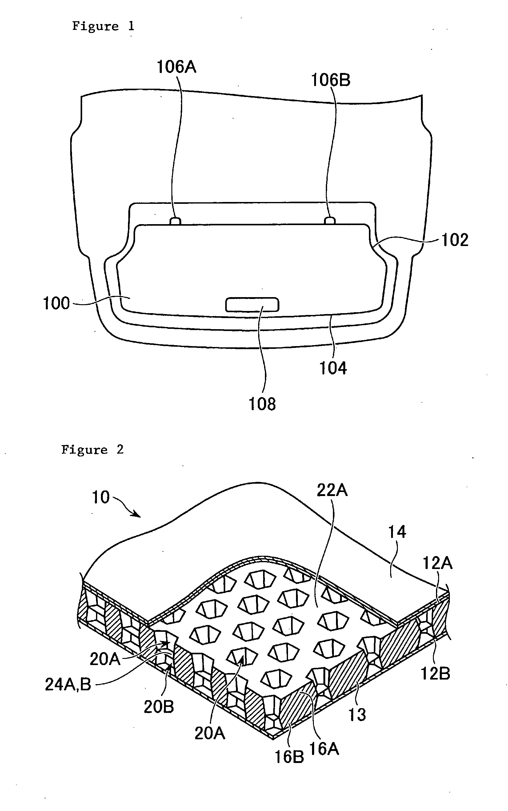
As shown in FIG. 1, the cargo floor lid 100 for the automobile requires a complicated profile because it has to be accommodated in a limited rear space. More specifically, a curved portion 102 with a small curvature for evading a tire house, a curved portion 104 with a large curvature along a rear shape of the automobile, and a local protrusion portion 106 constituting a hinge portion for closing and opening the cargo floor lid are necessary. In addition, a concave portion 108 on its surface constituting a g...


PUM

PropertyMeasurementUnit
Sizeaaaaaaaaaa
Lengthaaaaaaaaaa
Lengthaaaaaaaaaa

Abstract

An object of the present invention is to provide a core member for a sandwich panel and a method of forming the core member for the sandwich panel which are capable of attaining a desired profile, a desired pattern on its surface, and a desired inner structure in accordance with an application of the sandwich panel. According to an aspect of the invention, there is provided a thermoplastic resin core member interposed between two resin skin sheets comprising a closed hollow portion located to be inside of a desired position in accordance with an application of the sandwiched panel, and it is formed by clamping parison of a molten thermoplastic resin positioned to be between two split molds so as to exhibit a desired profile and / or a surface shape, two surfaces against each of which the molten parison is pressed to form an adhesive surface on which the corresponding resin skin sheet is formed.

Description

TECHNICAL FIELDThe present invention relates to a core member for a sandwich panel, a method of forming said core member for the sandwich panel, said sandwich panel and a method of forming said sandwich panel, in particular, it relates to the core member for the sandwich panel, the method of forming said core member for the sandwich panel which are capable of attaining a profile, a surface shape and an inner structure in a desired manner in accordance with an application of said sandwich panel, relating to the sandwich panel which is capable of reducing its weight and yet securing its strength due to the fact that the core member of which includes a hollow portion and yet secures its strength, while skin sheets of which includes a strength higher than that of the core member and secures a good adhesion properties between the core member and the skin sheet, and relates to the method of forming said sandwich panel which is capable of securing a sufficient strength and yet attaining an...

Claims


Application Information

Patent Timeline
IPC IPC(8): B32B3/30B29C70/68B32B3/28B32B3/12B32B3/10B32B1/08B29C48/07B29C48/09
CPCB29C43/00Y10T428/1393B29C43/203B29C47/0019B29C47/0023B29C47/0038B29C47/004B29C47/0054B29C49/0047B29C49/20B29C51/10B29C51/267B29C2043/023B29C2043/148B29C2043/3411B29C2043/3433B29C2049/2008B29C2049/2065B29C2049/2402B29C2791/006B29C2791/007B29K2105/06B29K2705/00B29L2031/3041B29L2031/608B29L2031/772B32B3/04B32B3/06B32B3/12B32B3/26B32B5/18Y10T428/24562Y10T428/24661Y10T428/24488Y10T428/24322B29C43/146Y10T428/24612Y10T428/24777Y10T428/233B29C48/07B29C48/001B29C48/09B29C48/0011B29C48/0017B29C49/251B29C49/0691E04C2/46E04C2/34E04C2/50
Inventor SUMI, TAKEHIKOTANJI, TADATOSHI
Owner KYORAKU CO LTD
Learn More