
Method for detecting and/or preventing grind burn

Active Publication Date: 2011-06-09
ALLISON TRANSMISSION INC
View PDF15 Cites 24 Cited by
  • Summary
  • Abstract
  • Description
  • Claims
  • Application Information

AI Technical Summary

Benefits of technology

[0015]In an alternative embodiment, a large-scale production method is provided for making gears. The method includes establishing tolerances for the amount of material removed from stock to form the gears. A grinding wheel is selected that maximizes cutting efficiency and requires infrequent dressing. Also, the number of passes the grinding wheel will make for removing material from the stock is determined. The method also includes establishing a threshold amount of coolant flow to be dispensed to the grinding wheel and stock during the grinding operation. The stock is ground by the grinding wheel during the grinding operation and gears are made from the stock. A condition favorable for generating grind burn on the gears is determined before, during, and after the grinding operation. If such a condition is determined, one or more parameters of the grinding operation is adjusted to eliminate the condition and the steps of grinding the stock with the grinding wheel, making gears, and determining a condition favorable for generating grind burn are repeated.
[0018]Another advantage of the inventive method is that every manufactured gear is tested for grind burn. More importantly, the grinding of each gear tooth is monitored for grind burn during the grinding operation. This allows immediate detection of grind burn and does not rely solely on visual inspection. Moreover, the inventive method can be implemented using tooling and resources available in the same manufacturing facility in which a gear or other ground workpiece is made. This can provide cost savings and test results much sooner than conventional detection processes which in some instances require finished parts to be shipped to an off-site test facility for testing.

Problems solved by technology

An electric field is induced in the grinding wheel and unwanted conditions that cause grind burn are detected.

Method used


Image

  • Method for detecting and/or preventing grind burn
  • Method for detecting and/or preventing grind burn
  • Method for detecting and/or preventing grind burn

Examples


Embodiment Construction

[0033]The embodiments of the present invention described below are not intended to be exhaustive or to limit the invention to the precise forms disclosed in the following detailed description. Rather, the embodiments are chosen and described so that others skilled in the art may appreciate and understand the principles and practices of the present invention.

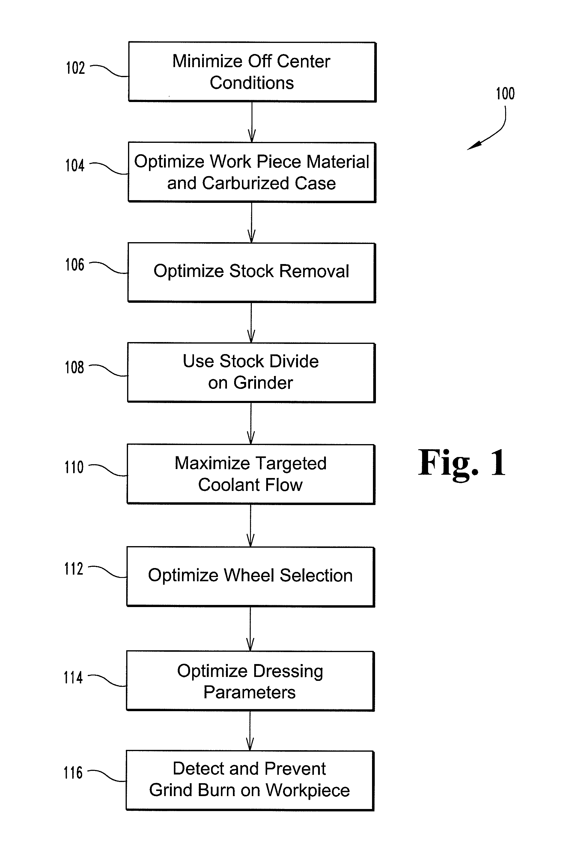
[0034]The present invention relates to a process control method of detecting and / or preventing grinding burns on a ground workpiece during and after a grinding operation. One of the purposes behind process control methods is to control the output of a specific process. In the case of manufacturing gears, for example, the process control method or system is designed to establish parameters for each step in the manufacturing process to ensure the manufactured gears are made substantially the same.

[0035]With reference to FIG. 1, an exemplary embodiment of a process control method is provided. While other process control methods may ...


PUM

PropertyMeasurementUnit
Electric potential / voltageaaaaaaaaaa
Thicknessaaaaaaaaaa

Abstract

The present invention provides a method of detecting and preventing grind burn from developing on a gear. The method includes performing acoustic emission testing while the gear is being ground during a grinding operation. The grinding wheel is evaluated during an eddy current test to detect material buildup on the grinding wheel which could cause grind burn. In addition, the method includes collecting swarf from the gear during the grinding operation and inspecting the swarf for an indication of grind burn.

Description

BACKGROUND[0001]The present invention relates to a grinding operation, and in particular, to a method of detecting and / or preventing grind burn on a workpiece being ground.[0002]The design and manufacture of bearings, gears, shafts and many other surface hardened components in modern automotive and aerospace industries pose significant challenges. These components require special attention in choosing the correct parameters for heat treatment as well as for subsequent machining processes. The latter, if carried out inaccurately, may reduce the surface hardness and diminish the compressive surface stresses after surface hardening. Accurate and continuous control of machining processes such as grinding is essential in today's production of these components.[0003]Grinding is a machining process used in the manufacture of high accuracy components to achieve the required tolerance. Compared with other machining processes, grinding requires a very large energy input per unit volume of mat...

Claims


Application Information

Patent Timeline
IPC IPC(8): B24B49/00B24B1/00B23F17/00B24B49/10B24B19/00
CPCB23F23/1218B24B1/00B24B19/009B24B53/075B24B49/105B24B49/18B24B49/003
Inventor FRAZEE, ELIZABETHHORVATH, PAUL
Owner ALLISON TRANSMISSION INC
Learn More