Heart support device

a technology of heart support and stent, which is applied in the field of heart support devices, can solve the problems of low degree of efficiency, blood damage to the patient by pumping work, and power supply to the electrically operated system, and achieve the effect of enhancing blood flow and reducing the volume of the first and second blood-conveying chambers

Active Publication Date: 2011-06-09
DEUTSCHES ZENTRUM FUER LUFT & RAUMFAHRT EV
View PDF6 Cites 4 Cited by
  • Summary
  • Abstract
  • Description
  • Claims
  • Application Information

AI Technical Summary

Benefits of technology

According to the disclosure, expansion of a fluid chamber of a ventricle will result in compression of the blood-conveying chamber of the same ventricle. In this manner, it is possible to convey blood into the blood circulation, while both the left and the right ventricle can be supported. A volume compensating reservoir compensating for the conveyed volume is not required.
In each of the above described heart support devices, use can be made of electric pumps as known from the state of the art. Advantageously, the electric pumps should have a low construction height and a high running performance.

Problems solved by technology

However, such heart support devices have to meet high demands with regard to the chosen technology and the tolerability of the implants.
For instance, the blood may happen to be damaged by the pumping work.
The power supply to the electrically operated systems, e.g. via cables passing through the abdominal wall, harbors a considerable risk of infection to the patient.
Further, low degrees of efficiency will cause high energy consumption and will heat the surrounding tissue.
Since it is not possible to exchange blood pumps quickly, such pumps must have a very high failure safety.
A disadvantage of the above described device resides in that the two hydraulic chambers, having two blood chambers arranged laterally adjacent thereto, as well as the hydraulic pump located between the hydraulic chambers, together have a large construction height and thus can be implanted into a patient's body only with considerably difficulty.

Method used


Image

  • Heart support device
  • Heart support device
  • Heart support device

Examples


Embodiment Construction

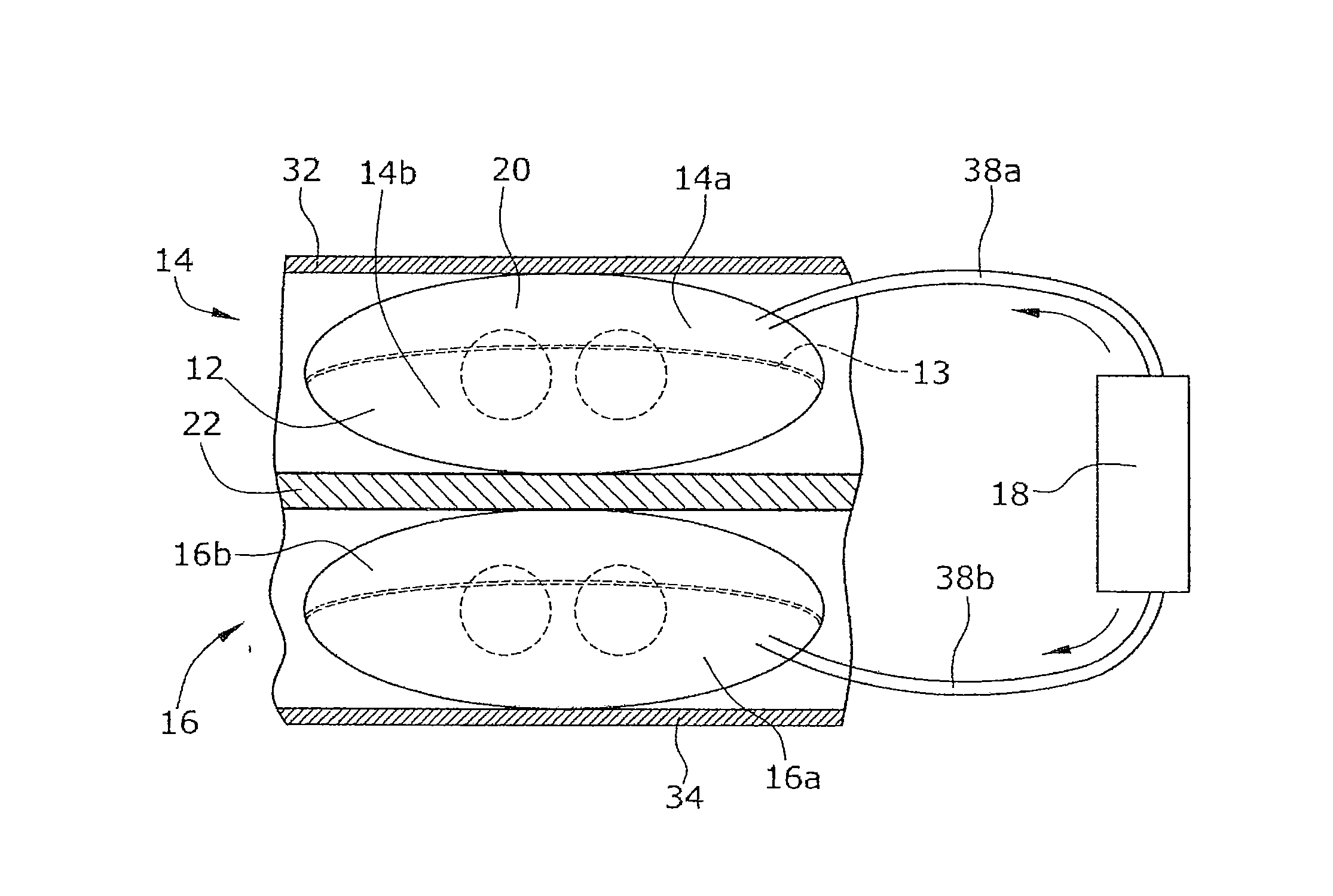
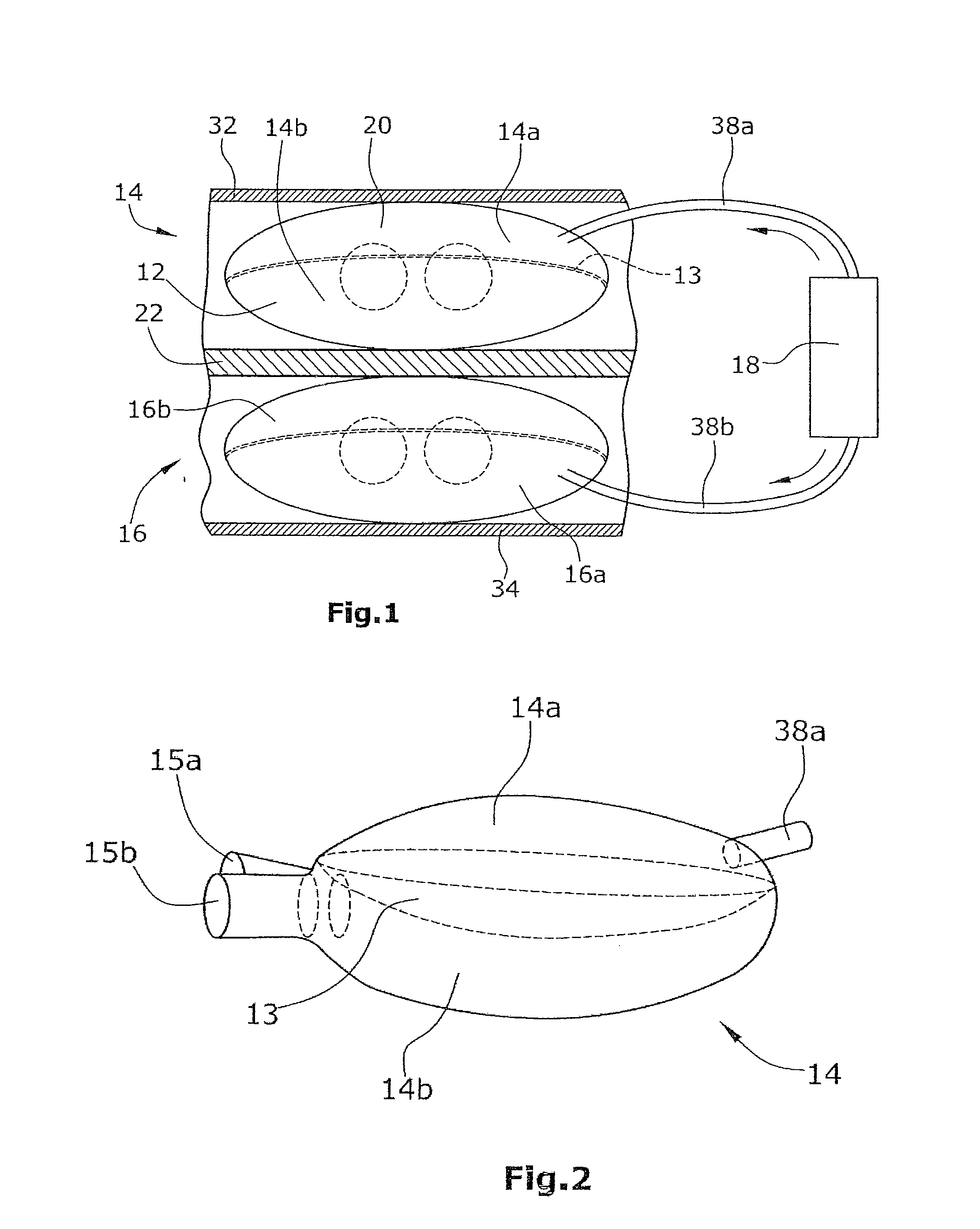
As shown in FIG. 1, a heart support device for pulsatile delivery of blood 12 comprises a first 14 and a second 16 ventricle. Each ventricle comprises a fluid chamber 14a,16a and a blood-conveying chamber 14b,16b. Said fluid chambers are filled with hydraulic liquid. Fluid chamber 14a is connected to a pump 18 via a fluid conduit 38a. Fluid chamber 16a is connected to pump 18 via a fluid conduit 38b. By means of pump 18, hydraulic liquid will be pumped alternately into said first and second fluid chambers 14a,16a, causing an alternate expansion of the two fluid chambers 14a,16a. Expansion of fluid chamber 14a of ventricle 14 will result in compression of blood-conveying chamber 14b of the same ventricle 14. The same applies to the second ventricle 16.

Pump 18 is arranged outside the first and second ventricles 14,16 as well as outside the first and second fluid chambers 14a,16a. As can be seen in FIG. 1, pump 18 is arranged, e.g., on the right-hand side of the two ventricles 14,16. T...


PUM


Abstract

A heart support device for pulsatile delivery of blood comprising a first and a second ventricle and a pump. Both ventricles comprises a fluid chamber and a blood-conveying chamber, wherein each fluid chamber can be filled with a fluid or emptied by way of the pump in such a way that an expansion or contraction of the fluid chamber occurs. In an expansion of the fluid chamber of a ventricle, a compression of the blood-conveying chamber of the same ventricle takes place, wherein a rigid pressure plate is disposed between a fluid chamber and the respective blood-conveying chamber, said pressure plate being able to move in the direction of the respective blood-conveying chamber.

Description

BACKGROUND1. Field of the InventionThe disclosure relates to a heart support device for pulsatile delivery of blood.2. Discussion of the Background Art Heart support devices, particularly mechanical systems for support of the blood circulation (VAD: Ventricular Assist Device) are implanted into the body of a patient suffering from cardiac insufficiency. Such devices will take over a part of the pumping work, thus stabilizing the blood circulation, e.g. until a donor organ has become available. Recent search has revealed that, during use of a heart support device, the cardiac function can improve to an extent favorable enough to allow for explantation of the system without subsequent heart transplantation.Artificial heart pumps can be adapted to the most diverse requirements and, in contrast to donor hearts, are readily available without a waiting period. However, such heart support devices have to meet high demands with regard to the chosen technology and the tolerability of the imp...

Claims


Application Information

Patent Timeline
Patent Type & Authority Applications(United States)
IPC IPC(8): A61M1/10A61M60/183A61M60/268A61M60/432
CPCA61M1/106A61M1/122A61M1/1063A61M60/432A61M60/148A61M60/183
Inventor VODERMAYER, BERNHARDWAGNER, HARALDSCHILLER, WOLFGANGSCHMID, THOMAS
Owner DEUTSCHES ZENTRUM FUER LUFT & RAUMFAHRT EV
Why Eureka
Try Eureka