Vector computer and instruction control method therefor

a vector computer and instruction control technology, applied in the field of vector computers, can solve the problems of complex procedures, inability to perform an overtaking control, and difficulty in detecting address dependency, so as to narrow down the access range of addresses and increase the number of overtaking patterns

Inactive Publication Date: 2011-06-09
NEC CORP
View PDF9 Cites 27 Cited by
  • Summary
  • Abstract
  • Description
  • Claims
  • Application Information

AI Technical Summary

Benefits of technology

[0019]Since the present invention is able to dynamically detect an address dependency source instruction with respect to vector gather/scatter instructions, it is possible to increase the number of overtaking patterns in comparison to static detection of an address dependency source instruction. This is because the present invention provides a possibility of allowing for an overtaking control on vector gather/scatter instructions which normall

Problems solved by technology

In this connection, vector gather instructions and vector scatter instructions perform memory accesses with elements of vector registers serving as effective addresses; hence, complex procedures are needed when calculating accessed areas and making overtaking determinations when executing instructions.
However, the technology of Patent Document 2 is unable to perform an overtaking control in the situation disab

Method used


Image

  • Vector computer and instruction control method therefor
  • Vector computer and instruction control method therefor
  • Vector computer and instruction control method therefor

Examples


first embodiment

1. First Embodiment

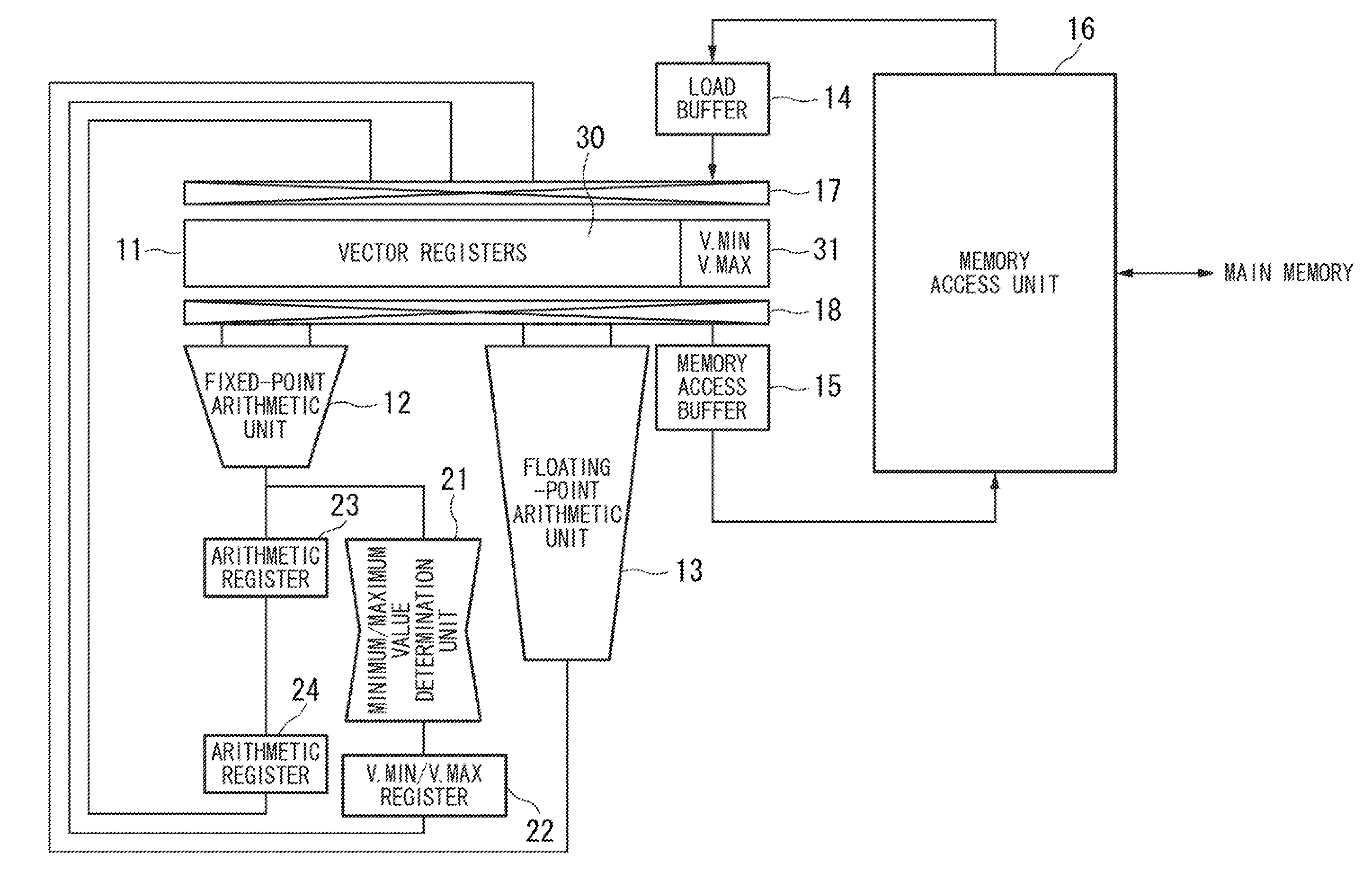
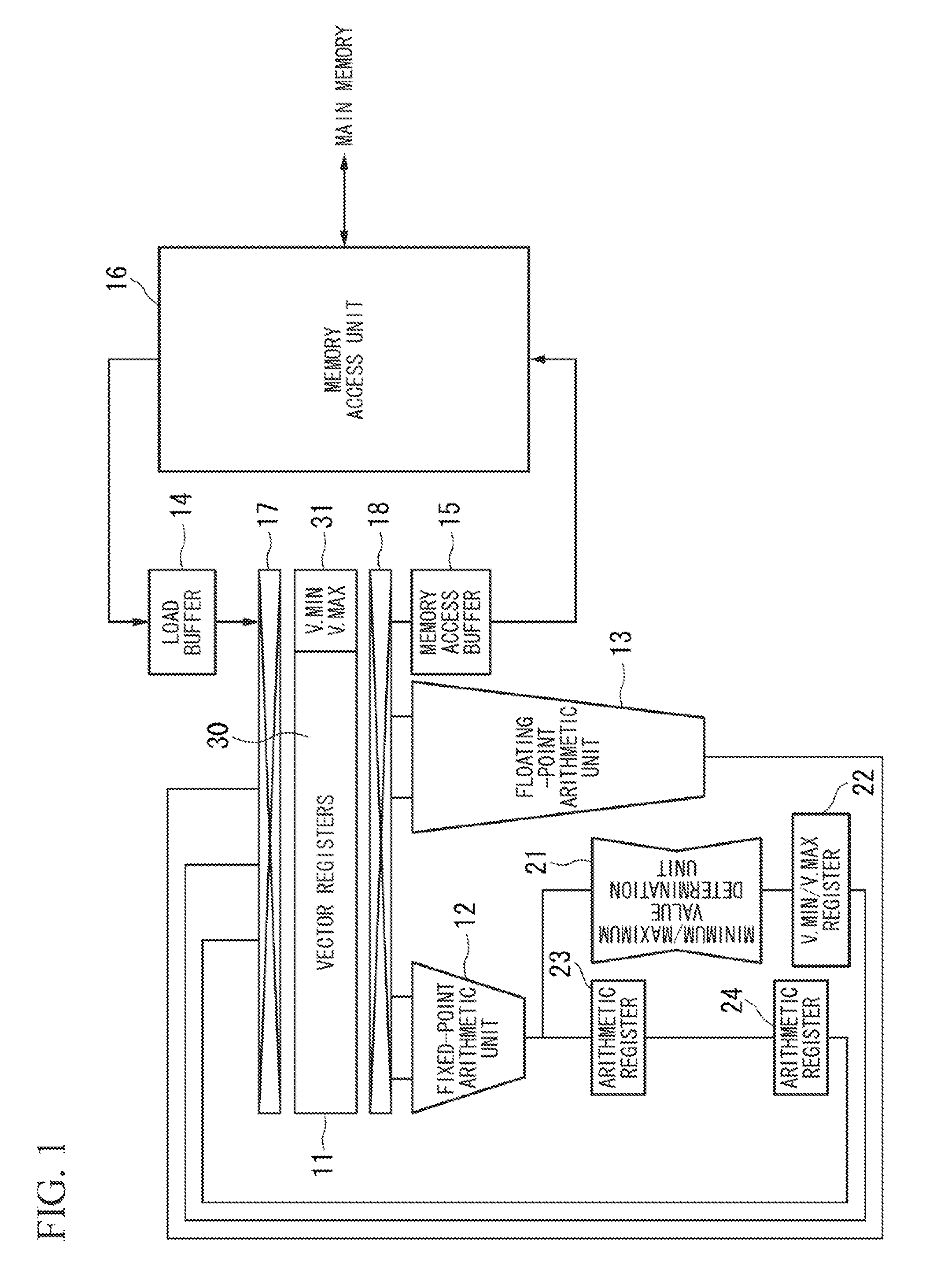
[0041]FIG. 1 is a block diagram showing the constitution of a vector computer according to a first embodiment of the present invention. The vector computer of the first embodiment is constituted of vector registers 11, a fixed-point arithmetic unit 12, a floating-point arithmetic unit 13, a load buffer 14, a memory access buffer 15, and a memory access unit 16, wherein functions of those blocks are similar to those of a conventionally-known vector computer. The vector computer further includes a minimum / maximum value determination unit 21, a minimum / maximum value register 22 (V.MIN / MAX), and arithmetic registers 23, 24 retaining arithmetic results.

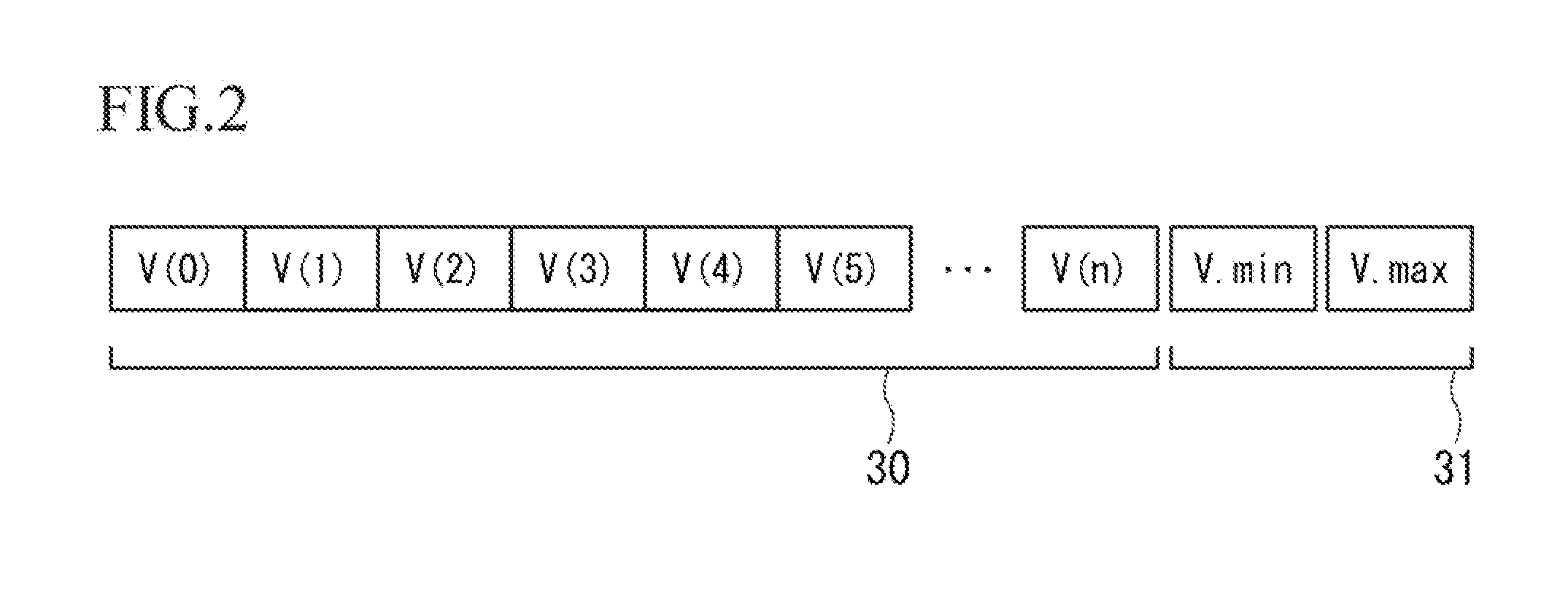
[0042]The vector registers 11 are each used for vector operations. Each vector register includes a plurality of elements (e.g. 128-512 elements). The functionality of each vector register 11 is divided into a main register section 30 and a minimum / maximum value register section 31 (V.min, V.max) retaining minimum / maximum...

second embodiment

2. Second Embodiment

[0092]In the first embodiment, address dependency source instructions regarding vector gather / scatter instructions are calculated via fixed-point calculations; hence, as shown in FIG. 9B, the minimum / maximum value determination unit 21 utilizes a difference of turnaround time (TAT) between the fixed-point calculation and the floating-point calculation so as to determine minimum / maximum values based on the calculation result of the fixed-point arithmetic unit 12.

[0093]Access addresses for vector gather / scatter instructions are practically calculated via the fixed-point calculation, whereas it is possible to execute vector gather / scatter instructions by use of loaded data of vector registers in accordance with a sequence of instructions as follows.

[0094]VLD $v7, 8, $s10;

[0095]VGT $v8, $v7;

[0096]A first line refers to a vector load instruction (VLD $v7, 8, $s10), in which upon loading data into the vector register ($v7), the vector register ($v7) performs a vector g...

third embodiment

3. Third Embodiment

[0103]FIG. 12 is a block diagram showing the constitution of a vector computer according to a third embodiment of the present invention. The vector computer of the third embodiment includes vector registers 211, a fixed-point arithmetic unit 212, a floating-point arithmetic unit 213, a load buffer 214, a memory access buffer 215, a memory access unit 216, a minimum / maximum value determination unit 221, a minimum / maximum value register 222 (V.min, V.max), arithmetic registers 223 and 224, and a secondary minimum / maximum value determination unit 225, which are equivalent to the vector registers 111, the fixed-point arithmetic unit 112, the floating-point arithmetic unit 113, the load buffer 114, the memory access buffer 115, the memory access unit 116, the minimum / maximum value determination unit 121, the minimum / maximum value register 122 (V.min, V.max), the arithmetic registers 123 and 124, and the secondary minimum / maximum value determination unit 125 in the vect...


PUM


Abstract

A vector computer executing vector operations via vector pipeline processing is restructured to dynamically perform an overtaking control on vector gather/scatter instructions. Minimum/maximum values among vector elements of vector registers are determined based on the result of fixed-point calculation defining an address dependency source instruction in accordance with a vector gather/scatter instruction, wherein minimum/maximum values are determined in a redundant time owing to a short turnaround time of the fixed-point calculation compared to floating-point calculation. An access range of addresses attributed to the vector gather/scatter instruction is specified based on minimum/maximum values. An overtaking control is performed on the vector gather/scatter instruction in light of the access range of addresses.

Description

[0001]The present application claims priority on Japanese Patent Application No. 2009-276535, the content of which is incorporated herein by reference.BACKGROUND OF THE INVENTION[0002]1. Field of the Invention[0003]The present invention relates to vector computers which perform vector operations via vector pipeline processing. In particular, the present invention relates to instruction control methods of vector computers such as overtaking controls of vector gather instructions and vector scatter instructions.[0004]2. Description of the Related Art[0005]Conventionally, vector processing methods aiming at high-speed processing have been designed to achieve high-speed memory accesses via overtaking controls, which allow memory accesses of subsequent load instructions to precede memory accesses of preceding store instructions when accessed areas of subsequent load instructions do not overlap accessed areas of preceding store instructions.[0006]Patent Document 1: Japanese Patent Applica...

Claims


Application Information

Patent Timeline
IPC IPC(8): G06F9/302
CPCG06F9/30036G06F9/30032G06F9/3001G06F9/30021G06F9/30043G06F9/345
Inventor KAWAGUCHI, EIICHIRO
Owner NEC CORP
Why Eureka
Try Eureka