Engine

a technology for engines and engines, applied in the field of engines, can solve problems such as difficult security, and achieve the effects of preventing the worsening of exhaust emissions, reducing fuel consumption, and optimizing the characteristics of fuel injection suitably

Inactive Publication Date: 2011-06-16
YANMAR POWER TECHNOLOGY CO LTD
View PDF9 Cites 3 Cited by
  • Summary
  • Abstract
  • Description
  • Claims
  • Application Information

AI Technical Summary

Benefits of technology

The present invention brings the following effects.
According to claim 1, by controlling the bypass valve based on the detection signal from the supercharger rotation sensor, the rotational speed of each of the compressors constituting the superchargers can be limited to be within the high-efficiency range of the supercharger. Accordingly, the intake air can be pressurized to the supercharging pressure corresponding to the operating state of the engine, whereby the fuel consumption can be reduced.
According to claim 2, by controlling the fuel injection nozzle based on the detection signal from the supercharger rotation sensor, the fuel injection characteristic can be optimized suitably. Accordingly, the fuel injection corresponding to the operating state of the engine can be realized, whereby the exhaust emission can be prevented from being worsened.
According to claim 3, by controlling the intake throttle based on the detection signals from the supercharging pressure sensor and the supercharger rotation sensor, it is not necessary to provide any bypass passage bypassing from the upstream side to the downstream side of the compressors constituting the superchargers. Accordingly, the construction of the engine can be simplified.
According to claim 4, by controlling the EGR valve based on the detection signals from the supercharging pressure sensor and the supercharger rotation sensor, the flow rate of the exhaust gas guided to the air intake passage can be optimized. Accordingly, the fuel injection corresponding to the operating state of the engine can be realized, whereby the exhaust emission can be prevented from being worsened.

Problems solved by technology

However, conventionally, in the engine having the superchargers, only the control is performed in which the supercharging pressure is limited corresponding to the operating state of the engine based on detection signals from an intake air flow rate sensor and a supercharging pressure sensor.
Therefore, in the engine having the two-stage supercharging system, it is difficult to secure the supercharging pressure corresponding to the operating state of the engine while limiting the rotational speed of each of the compressors constituting the superchargers to be within a high-efficiency range of the supercharger.Patent Literature 1: the Japanese Patent Laid Open Gazette 2004-92646

Method used


Image

  • Engine
  • Engine
  • Engine

Examples


first embodiment

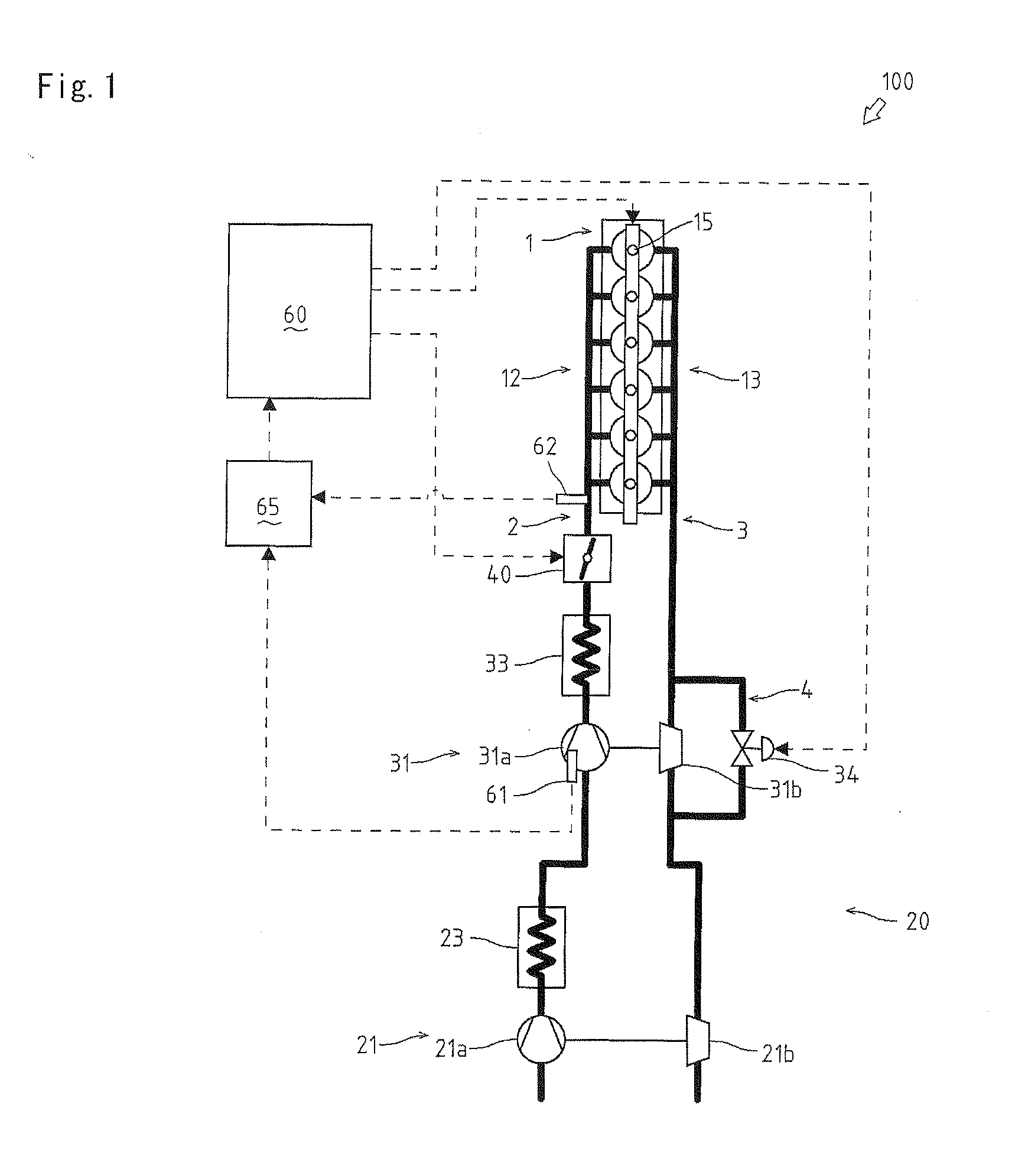
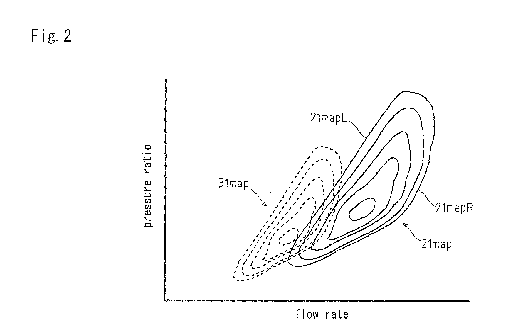
FIG. 1 is a schematic drawing of entire construction of an engine 100 having a two-stage supercharging system 20 according to the present invention. FIG. 2 is a graph of iso efficiency curves of compressor performance of superchargers 21 and 31. FIG. 3 is a flow chart of control construction of the superchargers 21 and 31.

second embodiment

FIG. 4 is a schematic drawing of entire construction of an engine 200 having the two-stage supercharging system 20 according to the present invention. FIG. 5 is a flow chart of control construction of superchargers 21 and 31.

third embodiment

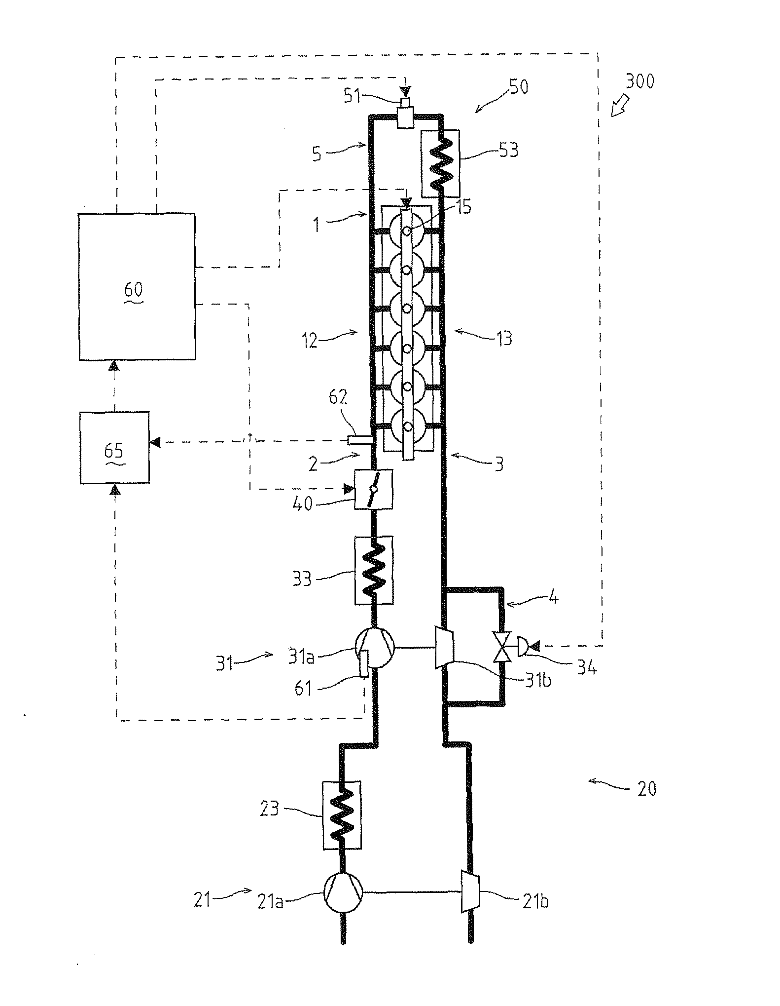
FIG. 6 is a schematic drawing of entire construction of an engine 300 having the two-stage supercharging system 20 according to the present invention. FIG. 7 is a flow chart of control construction of an EGR valve 51.

Explanation will be given on the construction of the engine 100 which is the first embodiment of the present invention referring to FIG. 1. The engine 100 is a direct injection type 6-cylindered engine having six combustion chambers, and mainly includes an engine body 1, an intake manifold 12 to which an air intake passage 2 is connected, an exhaust manifold 13 to which an exhaust gas passage 3 is connected, and fuel injection nozzles 15 injecting fuel to the combustion chambers. The fuel injection nozzles 15 can be controlled their fuel injection timing and the like by a control signal from a control device 60.

The engine 100 has the two-stage supercharging system 20. The two-stage supercharging system 20 has two superchargers, i.e. a low-pressure supercharger 21 and a ...


PUM


Abstract

Turbines (21b, 31b) and compressors (21a, 31a), which constitute superchargers (21, 31), are disposed in series on an exhaust gas passage (3) and an air intake passage (2), respectively. The supercharger (31) is equipped with a supercharger rotation sensor (61), which transmits a detection signal obtained according to the rotation of the compressor (31a) to a control device, a bypass passage (4), which bypasses exhaust gas from the upstream side to the downstream side of the turbine (31b), and a bypass valve (34), which regulates the flow rate of exhaust gas flowing through the bypass passage (4). Control device (60) regulates the rotational speed of the compressors (21a, 31a) in a high-efficiency range by producing a control signal based on the detection signal from the supercharger rotation sensor (61), and sending the control signal to the bypass valve (34).

Description

TECHNICAL FIELDThe present invention relates to an engine having a plurality of superchargers.BACKGROUND ARTConventionally, as an engine having a plurality of superchargers, an engine having a two-stage supercharging system is known. In the engine having the two-stage supercharging system, for example, turbines rotatively driven by receiving exhaust gas are arranged in one exhaust passage in series, and compressors pressurizing intake air are arranged in one intake passage in series. Bypass valves are provided in a bypass passage bypassing the exhaust gas from the upstream side to the downstream side of the turbines and a bypass passage bypassing the exhaust gas from the upstream side to the downstream side of the compressors, whereby the supercharging pressure can be limited by controlling the bypass valves (for example, see the Patent Literature 1).However, conventionally, in the engine having the superchargers, only the control is performed in which the supercharging pressure is ...

Claims


Application Information

Patent Timeline
Patent Type & Authority Applications(United States)
IPC IPC(8): F02D23/02
CPCF02B37/004F02B37/013F02B37/18Y02T10/144F02B2039/168F02D41/0007F02M25/0707F02B2037/122F02M26/05Y02T10/12
Inventor TAKAHASHI, TAKESHIKAWABE, TAKAONOMURA, HIDENORIOGATA, TOMOOSHIMIZU, KOUJIUKAI, SATOMI
Owner YANMAR POWER TECHNOLOGY CO LTD
Why Eureka
Try Eureka