burner

a burner and burner technology, applied in the field of burners, can solve the problems of difficult high-speed combustion control, etc., and achieve the effects of reducing manufacturing costs, excellent advantageous effects, and no backlash

Active Publication Date: 2011-06-16
IHI CORP
View PDF10 Cites 13 Cited by
  • Summary
  • Abstract
  • Description
  • Claims
  • Application Information

AI Technical Summary

Benefits of technology

[0039]Various excellent advantageous effects will be acquired. According to the invention, the burner is arranged axially of the burner throat on the furnace wall and comprises the nozzle body housed in the wind box and with the secondary air adjuster on the leading end of the nozzle body, the secondary air adjuster comprising the end plate for defining together with the near-furnace side surface of the wind box the cylindrical space opened in the outer circumference thereof, the slide damper axially slidable for surrounding the cylindrical space, the air vanes arranged at the predetermined intervals and circumferentially of the cylindrical space for swirling the secondary air and the drive means for slide movement of the slide damper. As a result, the air vanes are fixedly arranged; the configuration is simple; no backlash is generated over time; reduction in manufacturing cost is achieved and a stable swirling flow is acquired; and a stable combustion can be realized.
[0040]According to the invention, which provides a partition plate for axially partitioning said cylindrical space and said air vanes arranged circumferentially at predetermined intervals in at least one of partitioned small cylindrical spaces to swirl the secondary air, a swirling flow strength is adjustable with a simple configuration and a simple operation by adjusting and mixing airflows of the secondary air swirled and the secondary air not swirled.
[0041]According to the invention, in which the pressure loss adjusting means is arranged in a small cylindrical space with no air vanes among said small cylindrical spaces, a difference in pressure loss can be eliminated between the secondary air swirled and the secondary air not swirled to simplify the airflow rate adjustment.
[0042]According to the invention, in which said slide damper has an axial length at least blocking the small cylindrical space with no air vanes, the swirling strength of the supplied secondary air is adjustable.
[0043]According to the invention, in which said slide damper comprises a plurality of concentrically overlapping cylindrical bodies slidable independently on another, the opening state of the cylindrical space is diversified to enable a wide range of air adjustment.
[0044]According to the invention, in which said slide damper is capable of blocking the cylindrical space with the plurality of the cylindrical bodies, the secondary air is stoppable and a damper for a secondary air system can be eliminated.

Problems solved by technology

Thus, it is considered that highly accurate combustion control may become difficult.

Method used


Image

  • burner
  • burner
  • burner

Examples


first embodiment

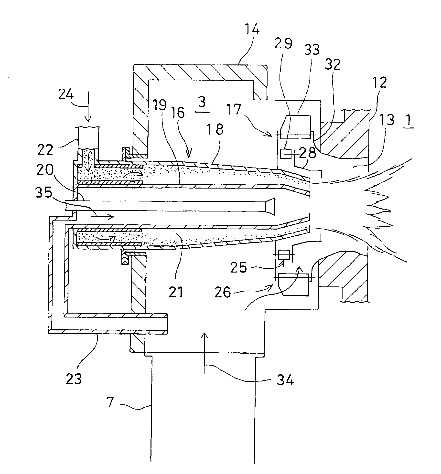
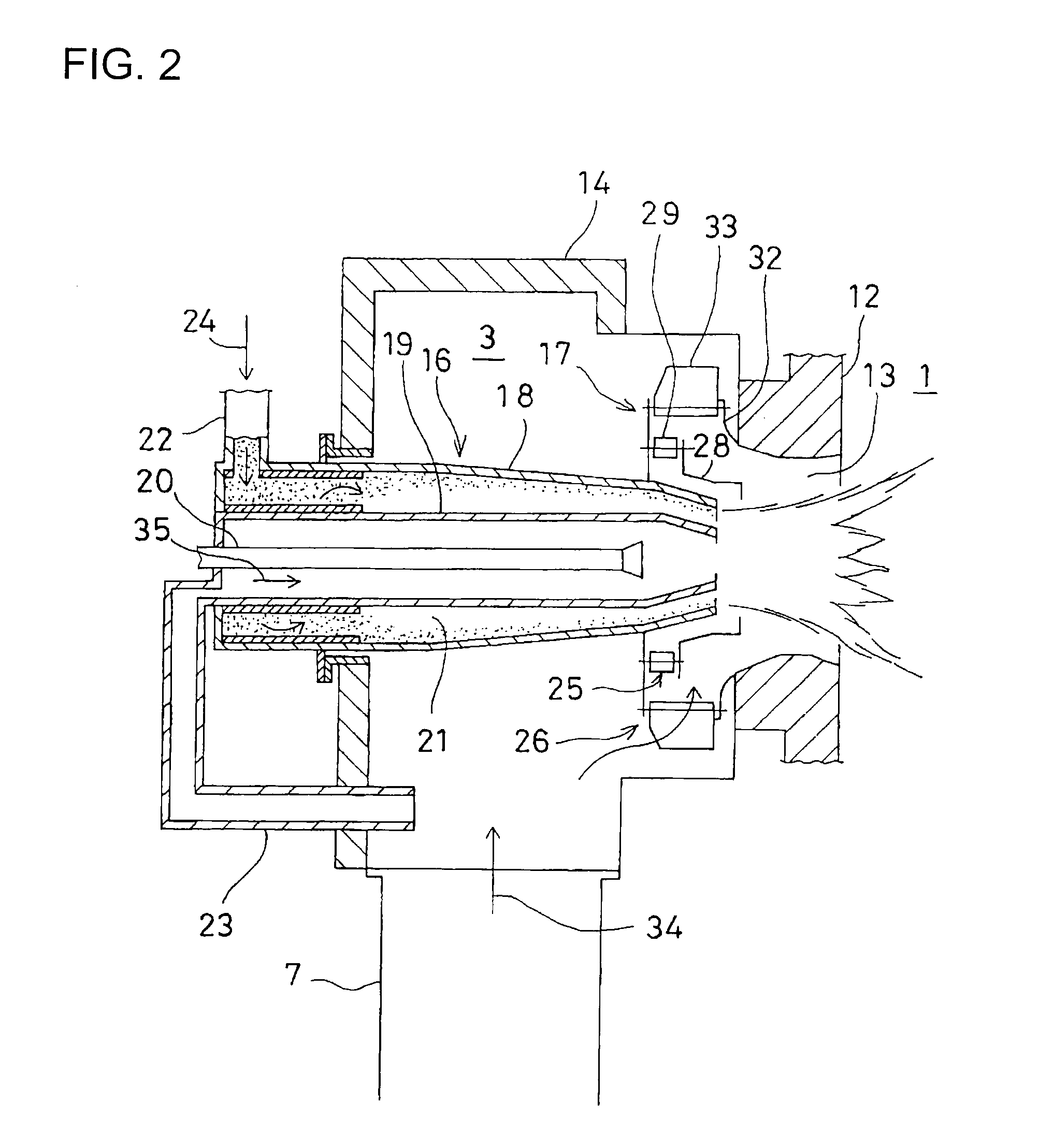
[0093]FIG. 3 shows the invention applied to a pulverized coal burner.

[0094]In the figure, parts equivalent to those shown in FIG. 2 are denoted by same reference numerals and will not be detailed.

[0095]A pulverized coal burner 15 is housed in a wind box 14 and an air adjuster 36 is arranged to house a leading end of a nozzle body 16. Through the wind box 14, secondary air 34 is taken in from surroundings of and swirled by the air adjuster 36 and flows out toward a throat 13.

[0096]Next, the air adjuster 36 will be described with reference to FIG. 4.

[0097]An end plate 37 is attached to an outer cylinder nozzle 18 at a position away from an furnace wall outer surface 39 (or a surface of the wind box 14 adjacent to the furnace) by a required distance. The end plate 37 is perpendicular to an axis of the nozzle body 16 and is disk-shaped concentrically of the nozzle body 16.

[0098]Arranged between the furnace wall outer surface 39 and the end plate 37 is a ring-shaped partition plate 38 wi...

second embodiment

[0113]FIG. 5 shows a In FIG. 5, parts equivalent to those shown in FIG. 3 are denoted by same reference numerals and will not be described.

[0114]In the second embodiment, a porous member 48 such as a punching metal or mesh is arranged on a circumference at which the away-furnace air induction chamber 47 is opened.

[0115]With a state where no porous member 48 is arranged, the secondary air 34 flowing into the near-furnace air induction chamber 46 has a pressure loss due to its passing through the air vanes 41 whereas the secondary air 34 flowing into the away-furnace air induction chamber 47 has no pressure loss since no resistance exists. Therefore, a supplied airflow rate varies between the blocking of the near-furnace air induction chamber 46 and the blocking of the away-furnace air induction chamber 47. Thus, the flow rate of blown air must be adjusted on the supplying side of the primary air 24 in accordance with the air adjustment by the slide damper 43; alternatively, airflow ...

third embodiment

[0117]FIG. 6 shows a In FIG. 6, parts equivalent to those shown in FIG. 3 are denoted by same reference numerals and will not be described.

[0118]In the third embodiment, the slide damper 43 has a divided configuration constituted by a plurality of cylindrical bodies to achieve diversification of the air adjustment by the air adjuster 36. Shown is a case of two-part configuration.

[0119]The slide damper 43 comprises first and second slide dampers 43a and 43b which are arranged like concentric circles and freely slidable without interfering with each other. The first and second slide dampers 43a and 43b are connected to and independently drivable by first and second actuators 44a and 44b, respectively.

[0120]An operation of the third embodiment will be described with reference to FIGS. 7 to 9.

[0121]When the first and second slide dampers 43a and 43b are overlapped with each other and the first and second slide dampers 43a and 43b are synchronizingly and integrally moved, the operation ...


PUM


Abstract

A burner is arranged axially of a burner throat on a furnace wall and includes a nozzle body housed in a wind box and with a secondary air adjuster on a leading end of the nozzle body. The adjuster includes an end plate for defining together with a near-furnace side surface of the wind box a cylindrical space opened in an outer circumference thereof, a slide damper axially slidable for surrounding the cylindrical space, air vanes arranged at predetermined intervals and circumferentially of the cylindrical space for swirling a secondary air and drive means and for slide movement of the slide damper.

Description

TECHNICAL FIELD[0001]The present invention relates to a burner on a wall surface of a boiler furnace to burn fuel such as pulverized coal or petroleum.BACKGROUND ART[0002]A wall surface of a boiler furnace is constituted by heat transfer pipes and is provided with a number of burners which burn pulverized coal, petroleum or other fuel in the furnace.[0003]FIG. 1 shows a schematic diagram of a boiler which uses pulverized coal as fuel.[0004]In FIG. 1, reference numeral 1 denotes a coal burning boiler furnace. In a lower portion of the furnace 1, pulverized coal burner groups 2 are arranged on plural stages (three stages are shown in FIG. 1). Each of the groups 2 includes a required number of pulverized coal burners 3 arranged horizontally along the wall surface.[0005]Arranged above (downstream of) the pulverized coal burner groups 2 are over air port groups 4 on required stages (shown as one stage in the figure). Each of the groups 4 is constituted by a required number of over air po...

Claims


Application Information

Patent Timeline
Patent Type & Authority Applications(United States)
IPC IPC(8): F23D1/00
CPCF23C7/004F23C7/008F23D2900/01001F23D2201/10F23D2900/00003F23D1/02
Inventor TAMURA, MASATOWATANABE, SHINJI
Owner IHI CORP
Why Eureka
Try Eureka