
Method for operating a continuous flow steam generator

a steam generator and continuous flow technology, applied in the direction of water circulation, water feed control, boiler control, etc., to achieve the effect of high valu

Active Publication Date: 2011-06-16
SIEMENS ENERGY GLOBAL GMBH & CO KG
View PDF58 Cites 20 Cited by
  • Summary
  • Abstract
  • Description
  • Claims
  • Application Information

AI Technical Summary

Benefits of technology

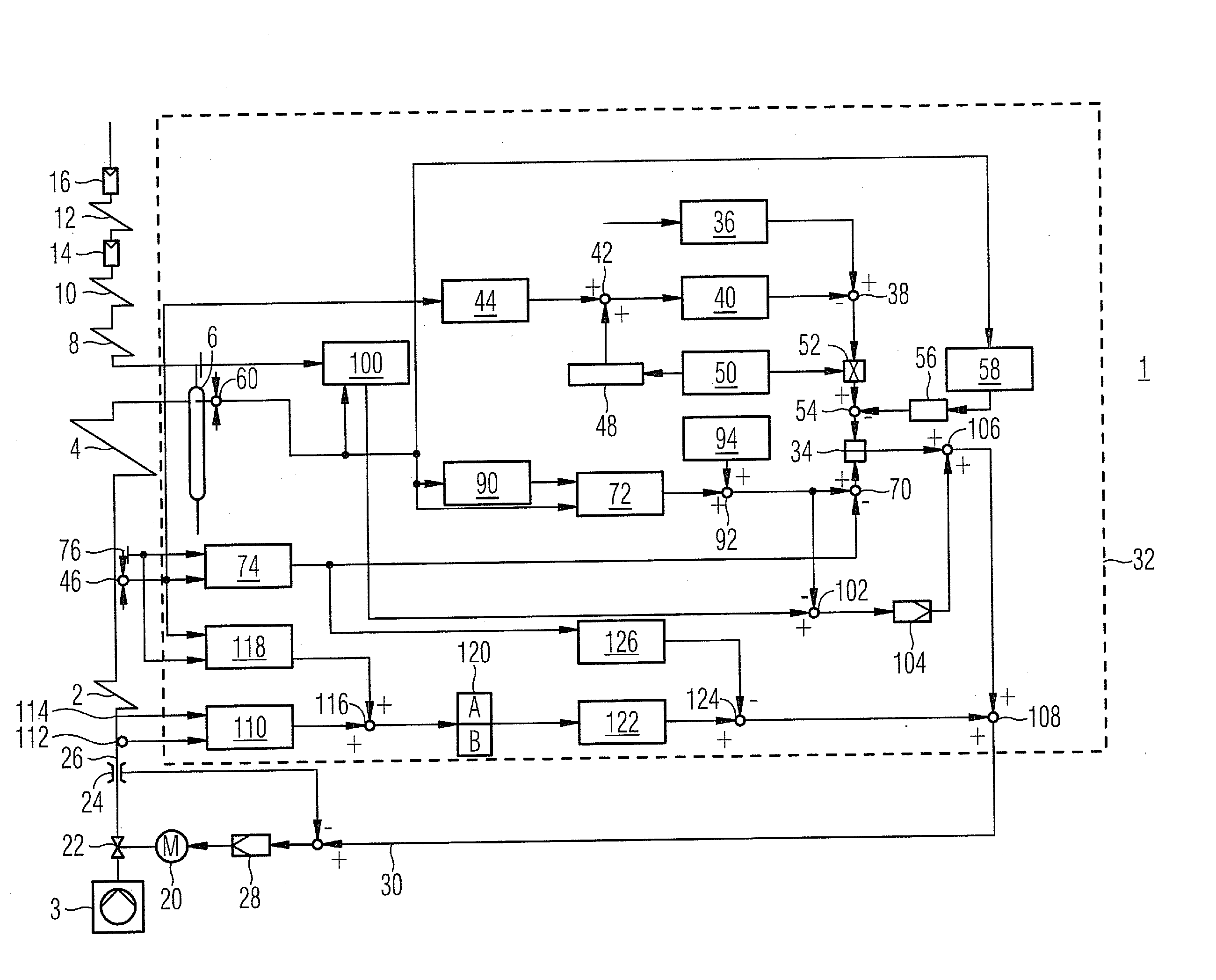
[0018]In order nonetheless to be able to respond to medium-side storage and release processes as a result of transient events in a suitable manner also in the region of the actual evaporator heating surface, it is advantageously provided to take into account in addition the change in the evaporator inlet enthalpy in a suitable manner when providing the correction value. In this case it is assumed that in the event of a reduction in the enthalpy at the evaporator inlet due to the cooling-down of the flow medium storage effects are to be expected which reduce the evaporator throughflow rate and are directly linked with an increase in the evaporator outlet enthalpy.
[0030]The advantages achieved by means of the invention are in particular that by taking into account the time derivative of the enthalpy or density of the flow medium at the input of one or more of the heating surfaces of the once-through steam generator it is made possible to correct the setpoint value for the feedwater mass flow determined as part of a predictive mass flow regulation, wherein suitable account can also be taken inter alia of the storage or release processes in the heating surfaces on the fluid or flow medium side, in particular in the preheaters. Particularly when load changes or other transient events occur in which such storage or release processes are to be expected, it is made possible to determine a demand-oriented setpoint value for the feedwater mass flow that has a particularly high value in qualitative terms.

Problems solved by technology

This means that under such conditions the throughflow rate through the respective heating surface and the mass flow conveyed by the feedwater pump no longer run in synchronism, with the result that in such circumstances more or less severe enthalpy fluctuations, which are undesirable per se, are to be expected at the evaporator outlet.

Method used


Image

  • Method for operating a continuous flow steam generator
  • Method for operating a continuous flow steam generator

Examples


Embodiment Construction

[0032]The forced-flow once-through steam generator 1 according to the FIGURE has a preheater 2, also referred to as an economizer, for feedwater provided as a flow medium which is contained in a gas flue that is not shown in greater detail. On the flow medium side a feedwater pump 3 is connected upstream and an evaporator heating surface 4 downstream of the preheater heating surface 2. On the output side the evaporator heating surface 4 is connected on the flow medium side via a water reservoir 6, which can also be embodied in particular as a water separator or separation vessel, to a plurality of downstream superheater heating surfaces 8, 10, 12 which for their part can be provided with injection coolers 14, 16 for the purpose of adjusting the steam temperatures and the like. The forced-flow once-through steam generator 1 is embodied as a heat recovery boiler or heat recovery steam generator, the heating surfaces, i.e. in particular the preheater heating surface 2, the evaporator h...


PUM


Abstract

A method for operating a continuous flow steam generator with an evaporator heating surface is provided. A target value for a supply water mass flow is fed to a device for adjusting the supply water mass flow. In order to improve the quality of a predictive supply water or mass flow control and to maintain the enthalpy of the flow medium at the evaporator outlet particularly stable especially when load changes occur, a correction factor is taken into consideration during production of the target value for the supply water mass flow. The correction factor is a characteristic of the temporal derivative of enthalpy or the density of the flow medium at the input of one or more heating surfaces.

Description

CROSS REFERENCE TO RELATED APPLICATIONS [0001]This application is the US National Stage of International Application No. PCT / EP2009 / 056469 filed May 27, 2009, and claims the benefit thereof. The International Application claims the benefits of European Patent Application No. 08010726.1 EP filed Jun. 12, 2008. All of the applications are incorporated by reference herein in their entirety.FIELD OF INVENTION [0002]The invention relates to a method for operating a once-through steam generator having a plurality of heating surfaces, wherein a setpoint value {dot over (M)}s for the feedwater mass flow {dot over (M)} is supplied to a device for adjusting the feedwater mass flow {dot over (M)}. The invention further relates to a forced-flow once-through steam generator for performing the method.BACKGROUND OF INVENTION [0003]In a once-through steam generator, heating a plurality of steam generator tubes which collectively form an evaporator heating surface leads to a complete evaporation of ...

Claims


Application Information

Patent Timeline
IPC IPC(8): F22B35/10F22D5/26F22D1/32
CPCF22B35/10Y02E20/16
Inventor BRUCKNER, JANFRANKE, JOACHIMTHOMAS, FRANK
Owner SIEMENS ENERGY GLOBAL GMBH & CO KG
Learn More