Heat Exchanger

a heat exchanger and plate technology, applied in heat exchanger fins, lighting and heating apparatus, laminated elements, etc., can solve the problems of not being able to use the entire width of the heat exchanger for the outlet duct, not being able to treat all the fluid to the same heat treatment, and ineffective heat transfer capacity of the heat exchanger. , to achieve the effect of reducing flow resistance, facilitating the exit of evaporated fluid, and increasing flow resistance in the distribution passag

Active Publication Date: 2011-06-16
ALFA LAVAL CORP AB
View PDF6 Cites 37 Cited by
  • Summary
  • Abstract
  • Description
  • Claims
  • Application Information

AI Technical Summary

Benefits of technology

[0018]In a further advantageous development of the inventive heat exchanger, the distance between the neutral plane of two adjacent distribution areas of the lower distribution passage is less than one press depth of the plate. A reduction of the distribution passage height will increase the flow resistance in the distribution passage. This will allow for an early evaporation of the fluid to be evaporated in the heat

Problems solved by technology

This is ineffective with respect of the heat transfer capacity of the plate heat exchanger.
As an inlet duct, intended for the heating fluid, must also extend through the upper part of the package of heat transfer plates, it has not been possible to use the

Method used


Image

  • Heat Exchanger
  • Heat Exchanger
  • Heat Exchanger

Examples


Embodiment Construction

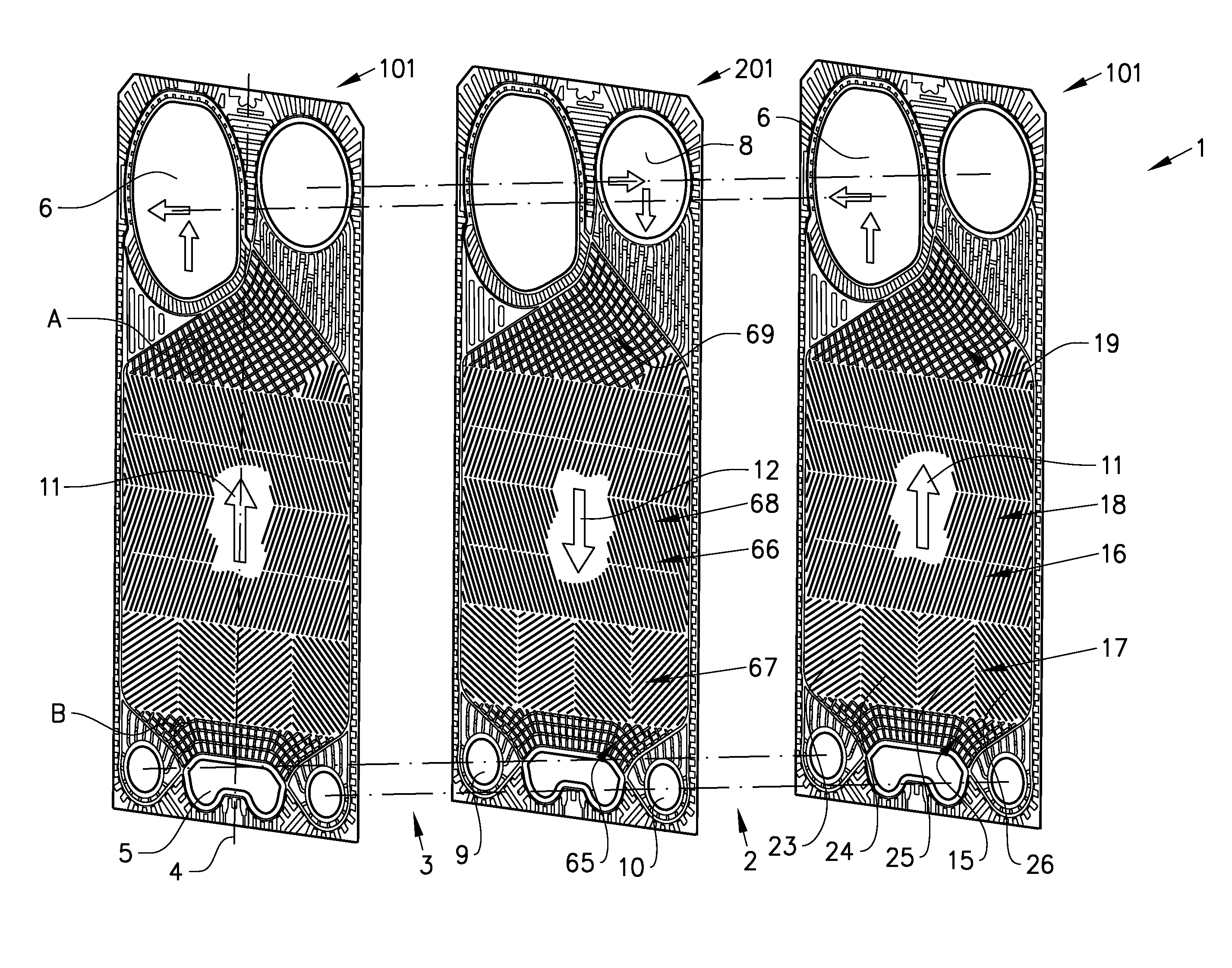
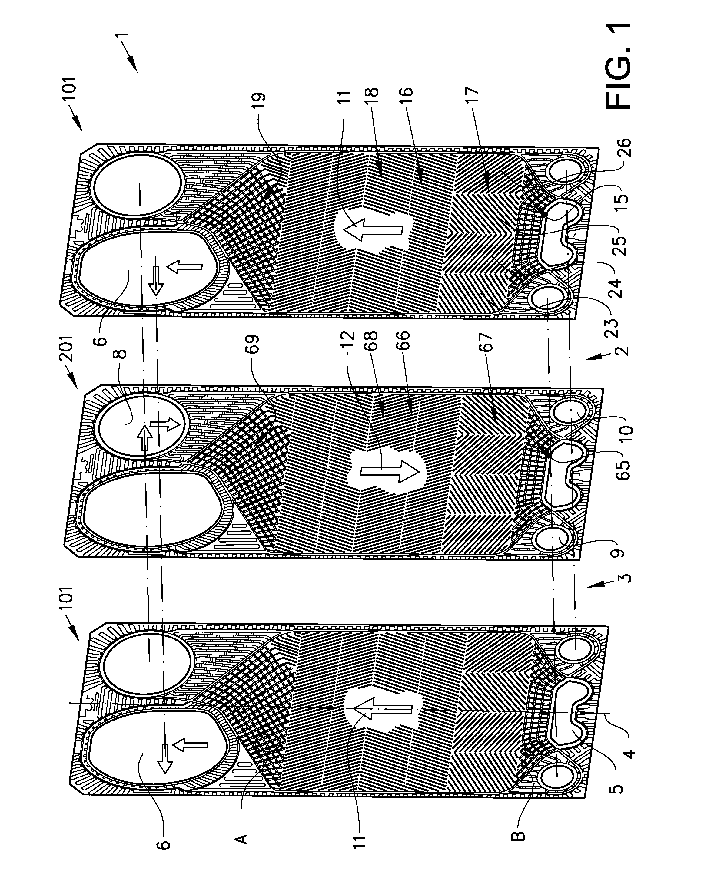
[0026]The embodiments of the invention with further developments described in the following are to be regarded only as examples and are in no way to limit the scope of the protection provided by the patent claims. The expressions lower, upper, vertical and horizontal used in the description refer to positions on a heat transfer plate when in use in an assembled heat exchanger. A reference to e.g. lower will thus refer to a detail positioned at the lower portion of a heat exchanger in use.

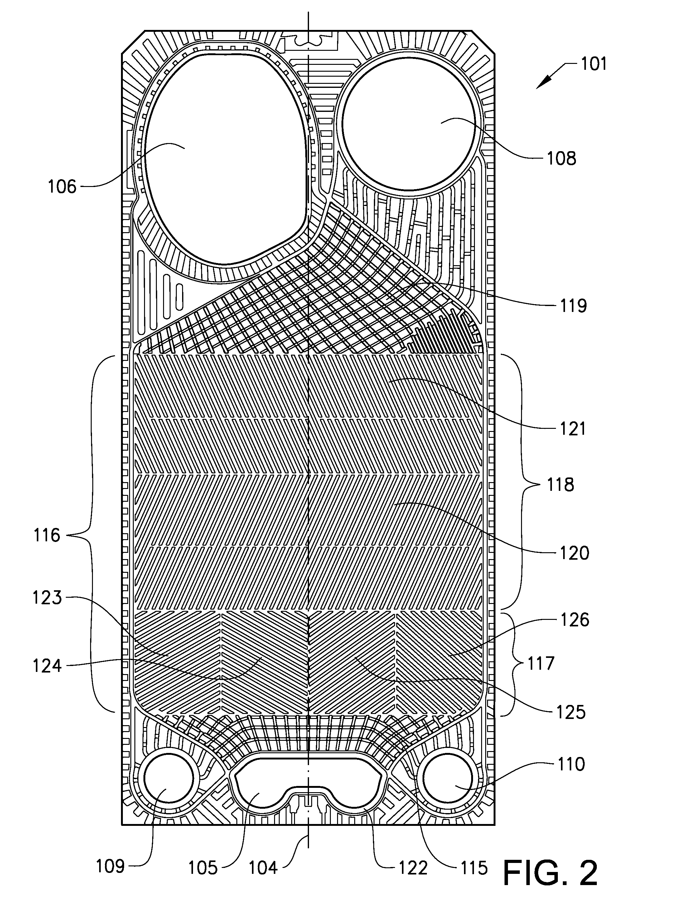
[0027]The plate heat exchanger assembly 1 shown in FIG. 1 comprises two types of rectangular, elongated heat transfer plates 101, 201 which have been provided with different corrugation patterns by means of pressing. The heat transfer plates, which are intended to be assembled in a frame in a conventional manner, may be provided with rubber gaskets along their edges to delimit flow channels between them, but as an alternative they could be permanently joined to each other, e.g. through soldering, we...


PUM


Abstract

The invention refers to a plate heat exchanger where the heat exchanger comprises a first flow channel between a first plate and a second plate, and where the flow channel comprises a first distribution passage, a heat transfer passage and a second distribution passage, where the heat transfer passage is vertically divided in a lower and an upper heat transfer passage and where the lower heat transfer passage is horizontally divided in a plurality of adjacent heat transfer zones, where the intermediate angle between the ridges and grooves in any of the heat transfer zones of the lower heat transfer passage is at least 30° larger than the intermediate angle of the upper heat transfer passage. The advantage of the invention is that an improved heat exchanger is provided, having an increased thermal performance and an improved evaporation capacity.

Description

TECHNICAL FIELD[0001]The present invention relates to a plate heat exchanger for evaporating a fluid.BACKGROUND ART[0002]The present invention relates to a plate heat exchanger for evaporating a fluid, comprising a package of abutting rectangular and essentially vertically arranged heat transfer plates, delimiting flow spaces between themselves and provided with corrugation patterns of ridges and grooves, said ridges intersectingly abutting each other in at least a part of each flow space and forming a number of supporting points between adjacent heat transfer plates, wherein each alternate flow space forms an evaporating passage, which evaporating passage has an inlet for fluid at its lower portion and an outlet for fluid and generated vapour at its upper portion near one of the vertical sides of the heat transfer plates, and the remaining flow spaces form passages for a heating fluid, which passages have inlets at their upper portions near the other vertical sides of the heat tran...

Claims


Application Information

Patent Timeline
IPC IPC(8): F28F3/04
CPCF28D9/005F28F2215/04F28F3/08F28F3/046F28F3/025F28F13/06F28F3/083
Inventor BLOMGREN, FREDRIKHOLM, MARTINKOVACS, TOMAS
Owner ALFA LAVAL CORP AB
Why Eureka
Try Eureka