

Process for producing spacer for liquid crystal display apparatus, ink for spacer formation, liquid crystal display appartus and process for manufacturing the same
a liquid crystal display and spacer technology, applied in non-linear optics, instruments, optics, etc., can solve problems such as display defects, display irregularities, display defects, etc., and achieve excellent positional precision and height precision, high positional precision, and sufficient height
- Summary
- Abstract
- Description
- Claims
- Application Information
AI Technical Summary
Benefits of technology
Problems solved by technology
Method used
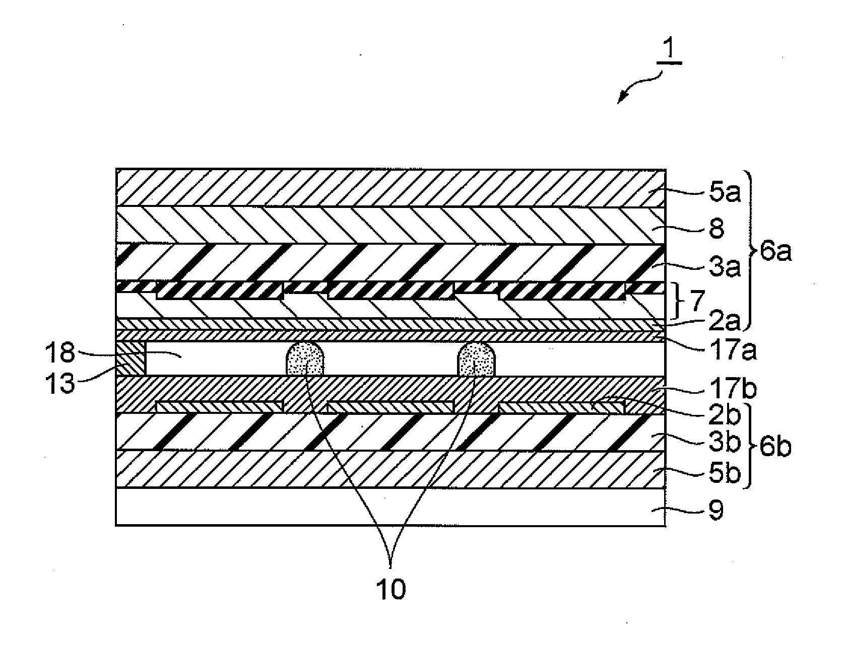
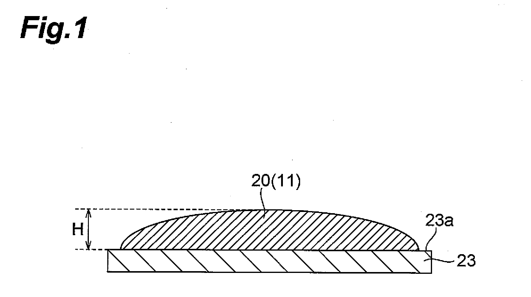
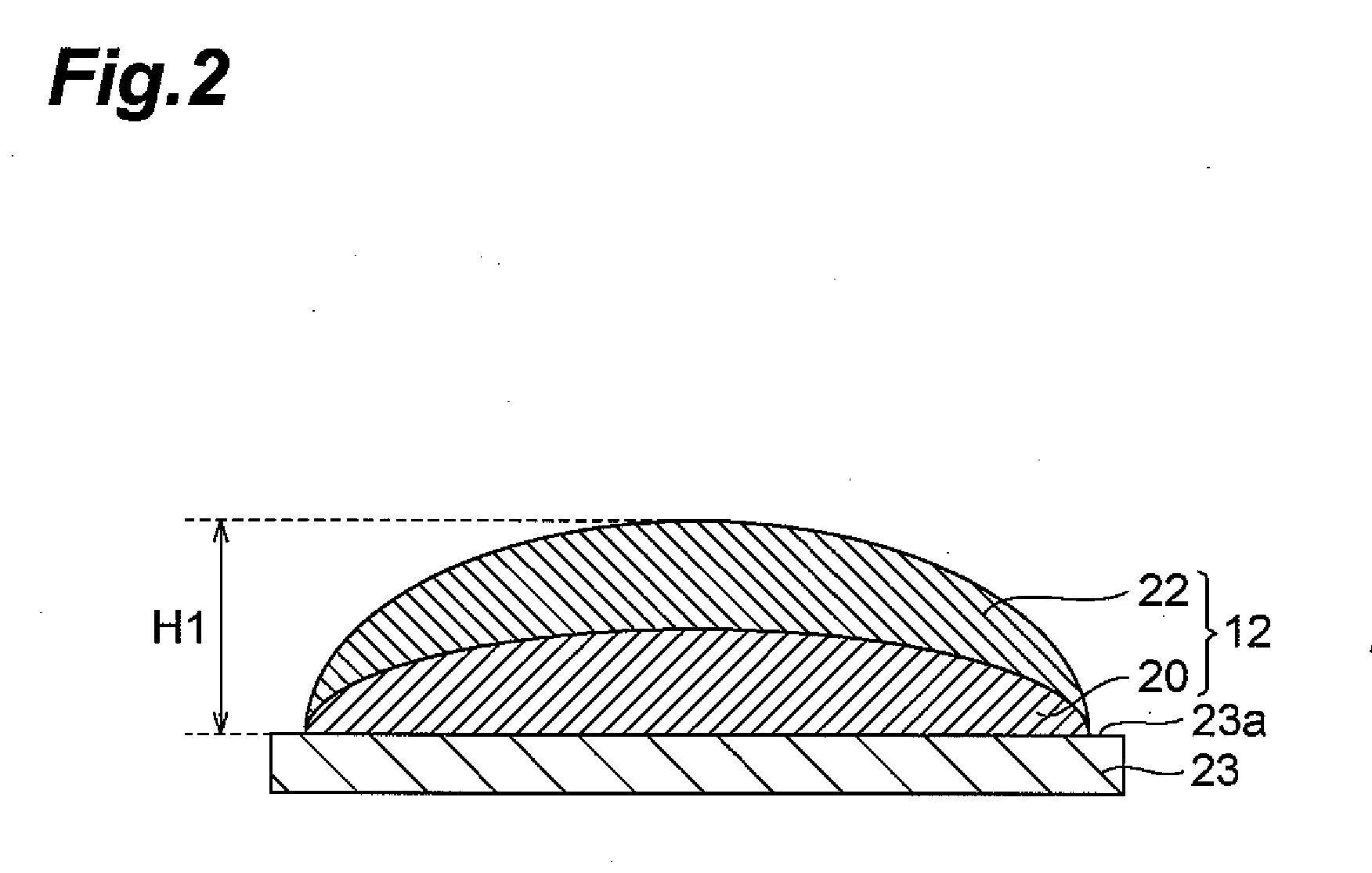
Image

Examples
example 1
[0092]The extraneous material was removed from ink 1 by filtration with a membrane filter having an aperture of 20 μm. Ink 1 from which the extraneous material had been removed was supplied to a piezo-type ink-jet apparatus equipped with a 50 μm-caliber head (trade name: Nanoprinter 1000, product of Microjet Corp.).
[0093][Printing of Ink for Spacer Formation and Formation of Spacer]
[0094]The ink-jet apparatus was used to print ink 1 on the surface of a substrate obtained by forming a VA liquid crystal oriented film on a glass plate (surface free energy: 29 mJ / m2) based on discharge position coordinates (target), with an interval of 150 μm and a droplet volume of 15 pL. After one printing of ink 1, the substrate was quickly transferred onto a hot plate that had been heated to 180° C., and was dried and hardened for 30 minutes to form a spacer. The properties of the ink and substrate used are shown in Table 2.
[0095][Evaluation of Positional Precision of Impact]
[0096]The coordinates of...
example 2
[0109]A spacer was formed on a substrate surface and evaluated in the same manner as Example 1, except that ink 2 was used instead of ink 1. The properties of the ink and substrate used are shown in Table 2. The evaluation results were as shown in Table 3.
example 3
[0110]A spacer was formed on a substrate and evaluated in the same manner as Example 1, except that the substrate used was obtained by forming a VA liquid crystal oriented film with a surface free energy of 35 mJ / m2 on the glass plate instead of the VA liquid crystal oriented film with a surface free energy of 29 mJ / m2. The properties of the ink and substrate used are shown in Table 2. The evaluation results were as shown in Table 3.
PUM
| Property | Measurement | Unit |
|---|---|---|
| viscosity | aaaaa | aaaaa |
| surface tension | aaaaa | aaaaa |
| vapor pressure | aaaaa | aaaaa |
Abstract
Description
Claims
Application Information