Optical detection device and electronic equipment

a detection device and optical technology, applied in the direction of optical elements, counting objects on conveyors, instruments, etc., can solve the problems of high cost of a control device for controlling electronic equipment, the operator is required to move to the vicinity of electronic equipment, and the operation of a remote controller of a car navigation device by a car driver, so as to facilitate the detection of a hand movement and avoid complicated image signal processing circuits. , the effect of simple configuration and arrangemen

Active Publication Date: 2011-06-16
SHARP KK
View PDF4 Cites 24 Cited by
  • Summary
  • Abstract
  • Description
  • Claims
  • Application Information

AI Technical Summary

Benefits of technology

[0062]As is apparent from the above, according to the present invention, it is possible to achieve a small inexpensive optical detection device that is capable of easily detecting a motion of a hand or the like of a human by a simple configuration and arrangement without complicated image signal processing circuits.
[0063]Also, according to the present invention, it is possible to achieve electronic equipment that is mounted with the optical detection device so as to be operable in noncontact manner.

Problems solved by technology

Operations in a contact method using switches, buttons, or the like have a drawback in that an operator is required to move to vicinity of the electronic equipment.
The noncontact method using a remote controller or the like also has various inconveniences, drawbacks and / or the like, such as necessity of a remote control transmitter, necessity of searching for the remote control transmitter before operation, especially, in AV (Audio Visual) equipment, necessity of washing dirty hands for cooking equipment, extremely high risk in operation of a remote controller of a car navigation device by a car driver, and the like.
In Patent Literatures 1 through 3 mentioned above, however, requirement of image recognition processing for recognition of an imaged subject as a hand, image signal processing for analysis of a motion of the hand, and the like leads to requirement of a sophisticated signal processing system for coping with various patterns and results in a high cost for a control device for controlling electronic equipment.
As in Patent Literatures 1 through 3, furthermore, image signal processing is required therein and thus involves the system with a large size and a large cost for a device for controlling electronic equipment.

Method used


Image

  • Optical detection device and electronic equipment
  • Optical detection device and electronic equipment
  • Optical detection device and electronic equipment

Examples


first embodiment

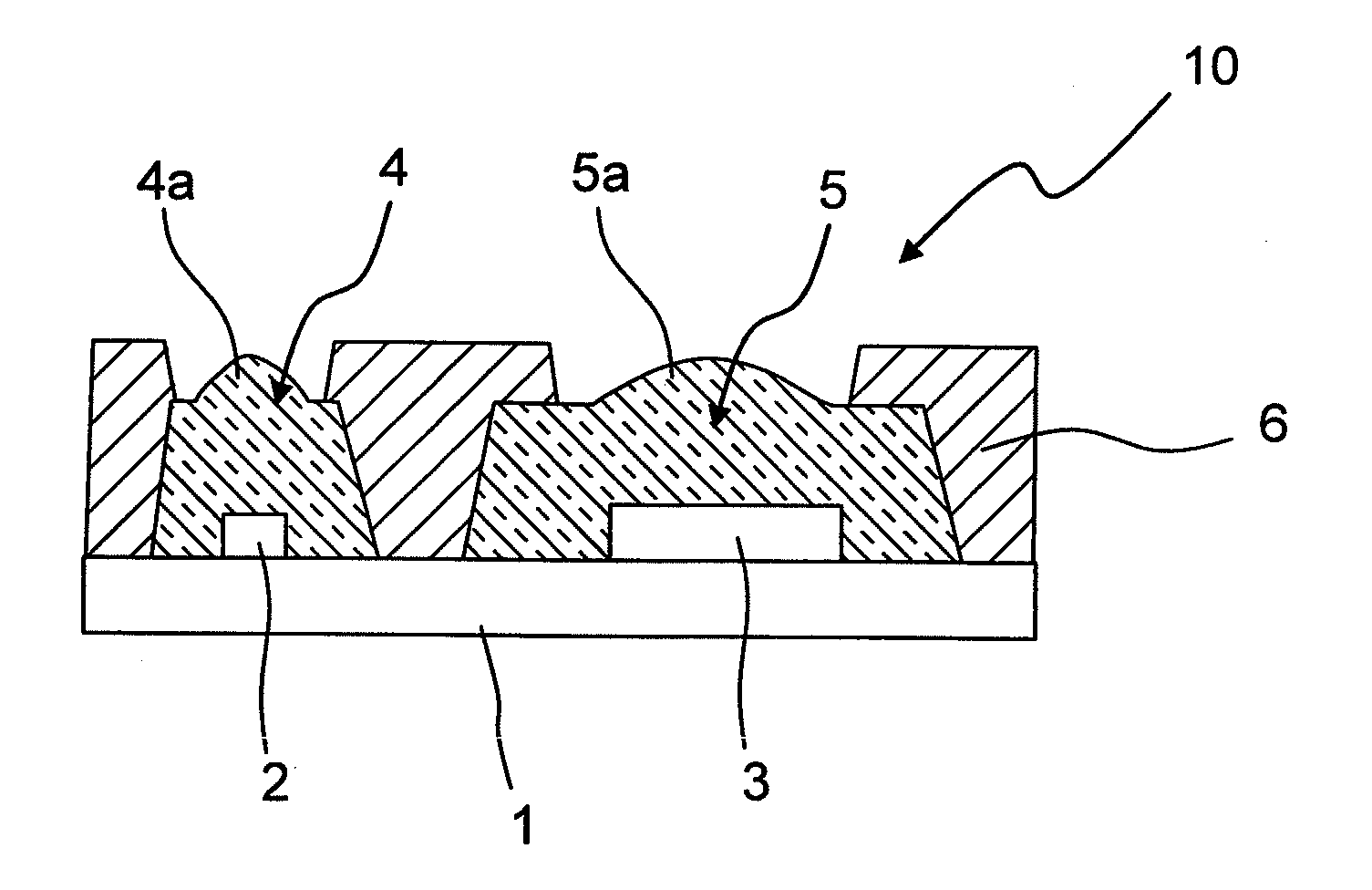
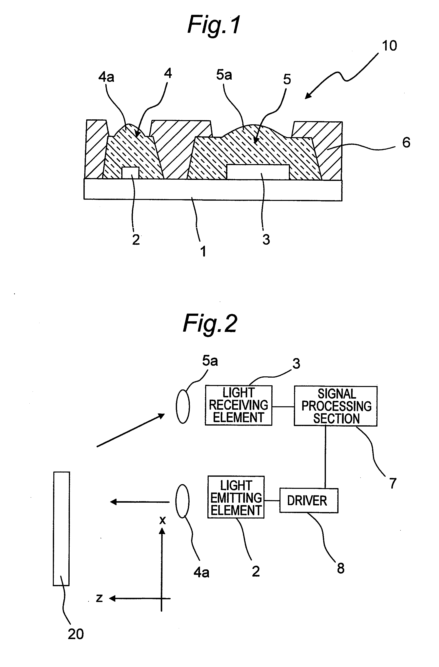
[0092]FIG. 1 is a sectional view showing a configuration of an optical detection device according to a first embodiment of the invention. As shown in FIG. 1, the optical detection device 10 of the first embodiment has a light emitting element 2 and a light receiving element 3 that are installed at a specified distance from each other on a substrate 1, a light-pervious resin part 4 that is molded out of light-pervious resin so as to cover the light emitting element 2, and a light-pervious resin part 5 that is molded out of light-pervious resin so as to cover the light receiving element 3. Formed in the light-pervious resin part 4 is a light emitting lens part 4a as an example of an irradiation optical system through which a bundle of emission rays is emitted from the light emitting element 2. Also, formed in the light-pervious resin part 5 is a light receiving lens part 5a as an example of a reflected light optical system on which reflected light is incident. The optical detection de...

second embodiment

[0127]FIG. 10 is a schematic view showing an optical detection device according to a second embodiment of the invention. The optical detection device 10 of this second embodiment is similar in configuration to the optical detection device 10 of the first embodiment, and so like component members are designated by like reference signs.

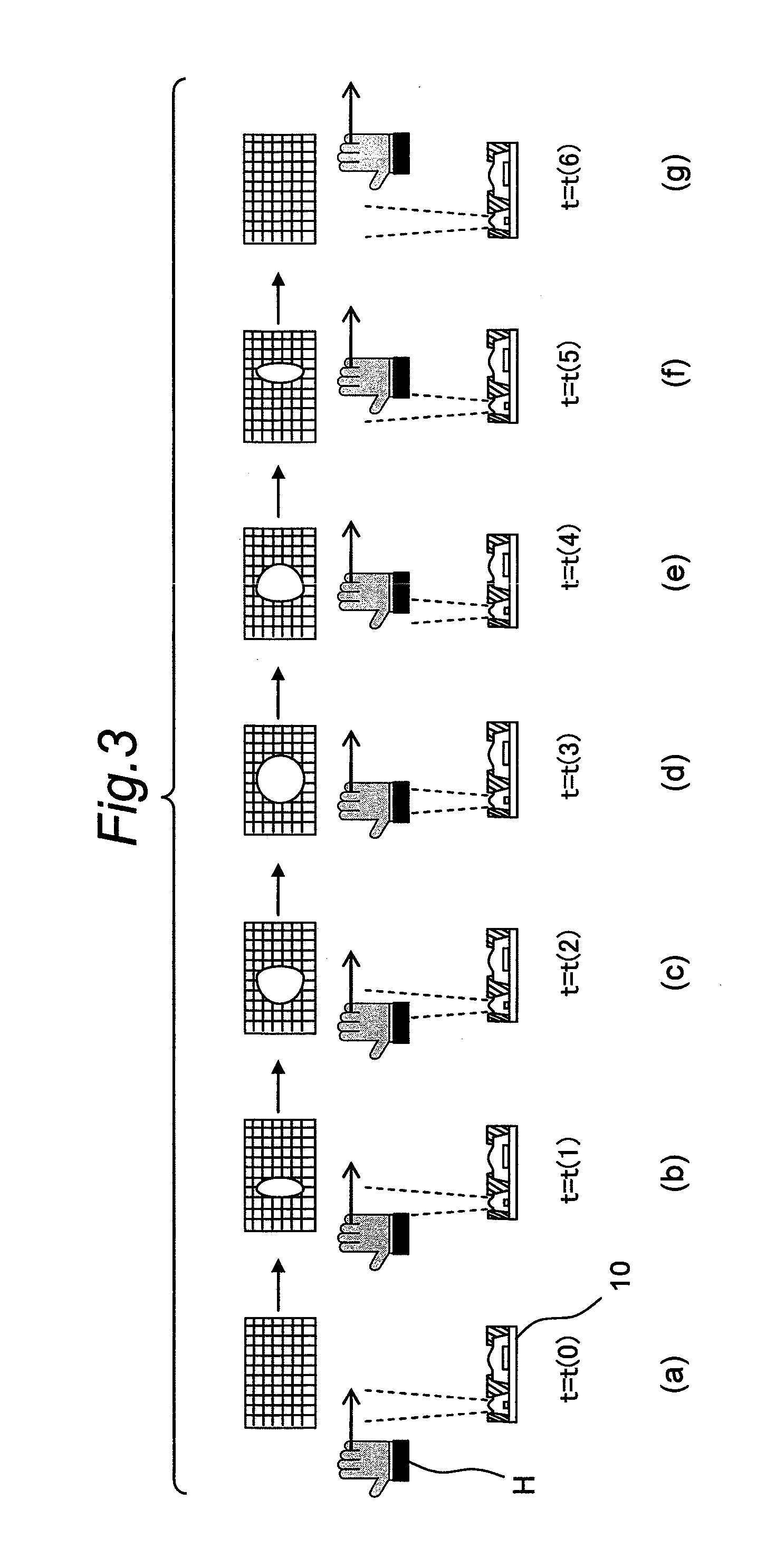
[0128]As shown in FIG. 10, a direction in which a light emitting lens part 4a and a light receiving lens part 5a of the optical detection device 10 are arrayed is assumed as an x-axis, a direction in which a bundle 12 of emission rays is emitted is assumed as a z-axis, and a straight line which is perpendicular to a plane containing the x-axis and the z-axis and which passes an intersection point of the x-axis and the z-axis is assumed as a y-axis. It is assumed that an object H to be measured (a human hand in this embodiment) is to make two-dimensional move, or motion, in the x- and y-directions along a plane of an arbitrary z-coordinate, as shown in F...

third embodiment

[0134]FIG. 14 is a schematic view showing an outlined configuration of an optical detection device according to a third embodiment of the invention. The optical detection device of this third embodiment is similar in configuration to the optical detection devices of the first and second embodiments except the computational function of the signal processing section 7 (shown in FIG. 2), and so like component members are designated by like reference signs. The signal processing section 7 of the optical detection device of the third embodiment has a function of computing a distance from a light-spot position on the light receiving element 3 to the object 20 to be measured, differing in this point from the optical detection devices of the first and second embodiments.

[0135]As shown in FIG. 14, a point O is a center of the light emitting lens part 4a, a point A is a point at which an axis of light emission intersects with the object 20 to be measured, a point B is a center of the light re...


PUM


Abstract

An optical detection device includes a light emitting element, which is an area sensor, a light emitting lens part for irradiating an object to be measured with a bundle of emission rays emitted from the light emitting element, a light receiving lens part for condensing reflected light from the object, a light receiving element for detecting reflected light from the object condensed by the light receiving lens part, and a signal processing section for processing a light-reception signal from the light receiving element. Based on the light-reception signal from the light receiving element, the signal processing section detects at least one of an x-coordinate or a y-coordinate of the object on an x-y coordinate plane from at least one of a light-spot position or a light-spot shape on the light receiving element.

Description

TECHNICAL FIELD[0001]The present invention relates to an optical detection device and electronic equipment and particularly to an optical detection device that is capable of detecting spatial position information of an object to be measured and detecting transition information of the object to be measured by measuring change with lapse of time in the spatial position information. The optical detection device of the invention is suitable for use as a control device for noncontact operation of electronic equipment, to which the present invention also relates, and particularly to electronic equipment, such as video equipment, audio equipment, and air conditioning equipment, in which the optical detection device detects positions of humans in order that operational status of the equipment may be optimized for the humans, and electronic equipment mounted with a noncontact motion controller which operates a car navigation device, mobile equipment, household electric cooking appliances or ...

Claims


Application Information

Patent Timeline
Patent Type & Authority Applications(United States)
IPC IPC(8): G01B11/14
CPCG06F3/0304G06F3/011
Inventor WADA, HIDEOYAMAGUCHI, AKIFUMIKUBO, MASARU
Owner SHARP KK
Why Eureka
Try Eureka