Turbine Engine Airfoil and Platform Assembly

a technology for turbine engines and platforms, which is applied in the direction of liquid fuel engines, vessel construction, marine propulsion, etc., can solve the problems of angle grain boundaries, casting defects, and disadvantages of one piece casting of blades and platforms

Inactive Publication Date: 2011-06-16
SIEMENS ENERGY INC
View PDF16 Cites 60 Cited by
  • Summary
  • Abstract
  • Description
  • Claims
  • Application Information

AI Technical Summary

Problems solved by technology

However, casting the blade and platform in one piece has disadvantages.
The thermal gradient is not optimized when the baffle does not closely fit around the casting and can lead to the formation of casting defects such as low and high angle grain boundaries.
It is also difficult to maintain the single crystal structure in regions where there are large geometric changes in the casting, for example in the fillet region where the airfoil transitions to the platform, and in the root / shank below the platform.
Casting defects such as ‘freckle chains’ are often observed.
Forming the blade and platform as a single piece does not allow material optimization.
However, forming them of separate pieces involves fastening, close tolerances, stress concentrations, and vibration issues.

Method used


Image

  • Turbine Engine Airfoil and Platform Assembly
  • Turbine Engine Airfoil and Platform Assembly
  • Turbine Engine Airfoil and Platform Assembly

Examples


Embodiment Construction

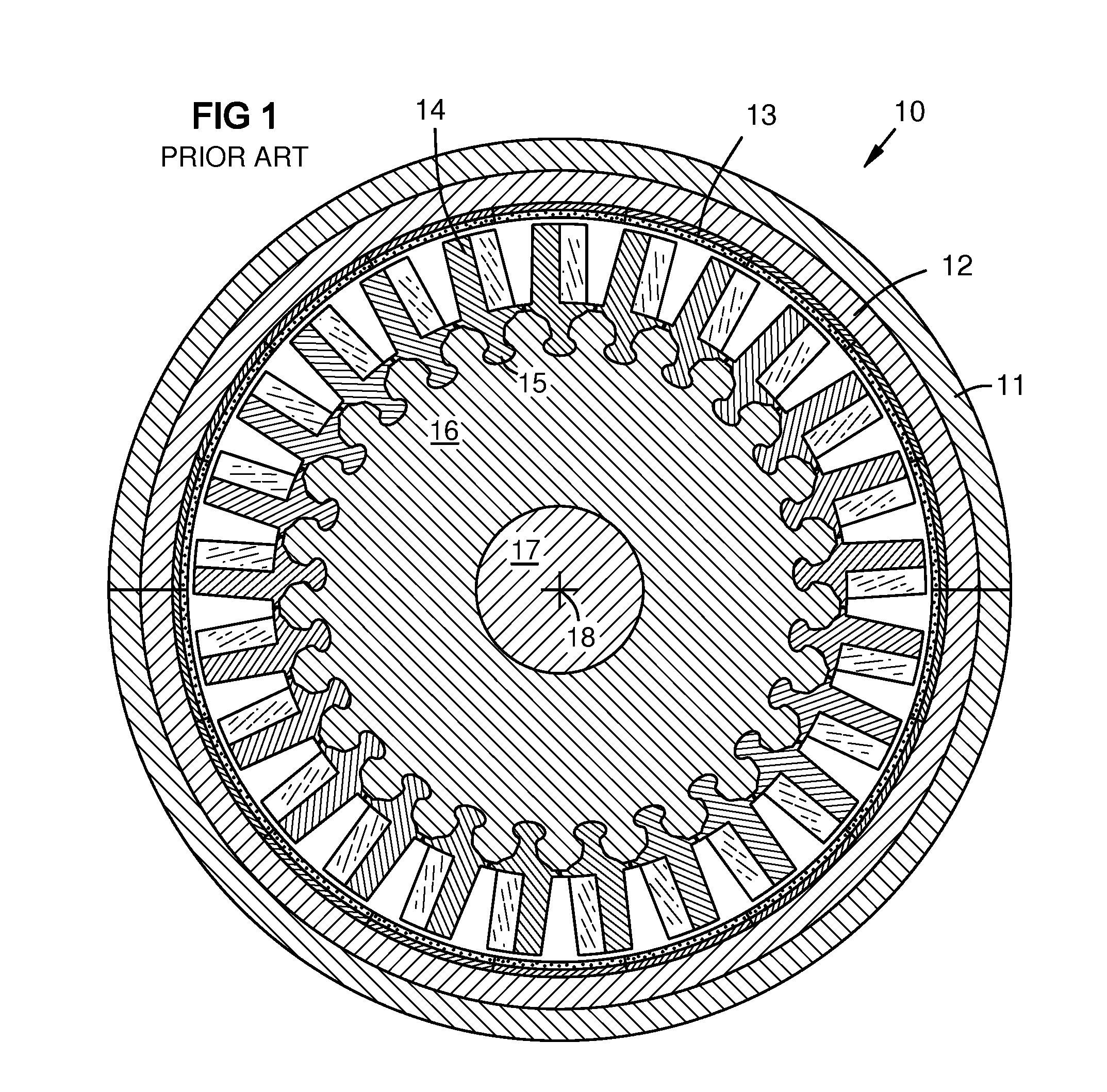
[0013]FIG. 1 shows conceptual sectional view of a known gas turbine engine 10 with a casing 11, retaining ring 12, and shroud 13, taken through a turbine rotor disk 16. Blades 14 with integral platforms 15 are mounted around the disk using a dovetail joint geometry. The disk is mounted on an axle 17 having an axis 18.

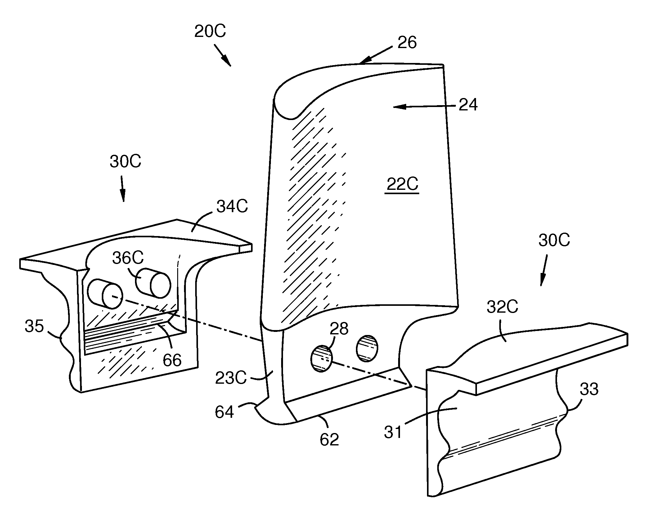
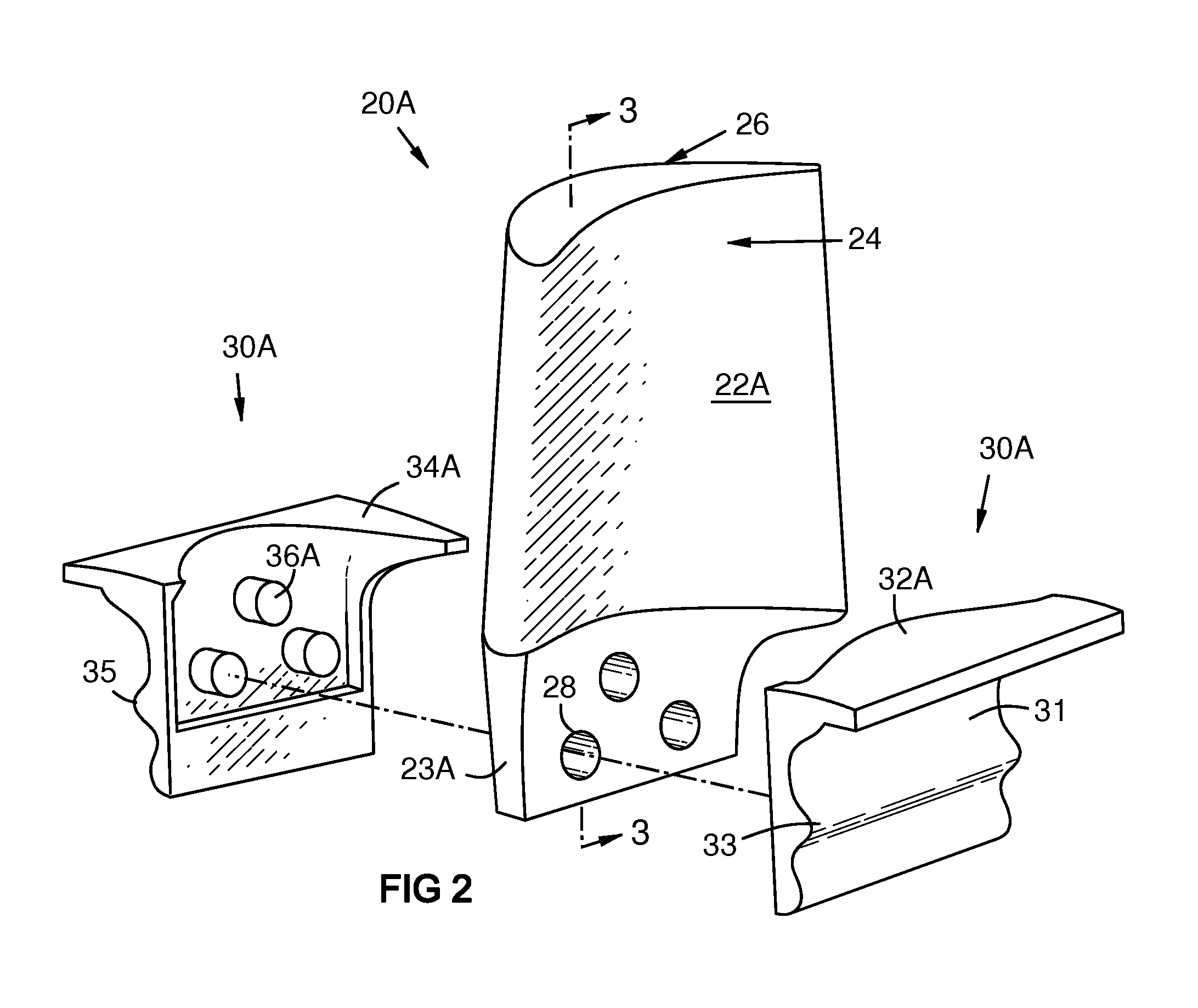
[0014]FIG. 2 shows a turbine blade assembly 20A, including an airfoil 22A having a pressure side 24, a suction side 26, and a blade shank 23A with at least one pin hole 28. A blade platform 30A has an outer surface 31, a pressure side portion 32A with at least one laterally extending tooth 33, and a suction side portion 34A with at least one laterally extending tooth 35. One or both of these platform portions have one or more pins 36A that fit the pin holes 28. After assembly, the platform 30A surrounds or brackets the blade shank 23A. The pins 36A do not extend to the outer surface 31 of the platform 30A. They may be integrally formed with the platform, reducing the th...


PUM

PropertyMeasurementUnit
castabilityaaaaaaaaaa
pressureaaaaaaaaaa
heat toleranceaaaaaaaaaa

Abstract

A turbine airfoil (22A) is formed by a first process using a first material. A platform (30A) is formed by a second process using a second material that may be different from the first material. The platform (30A) is assembled around a shank (23A) of the airfoil. One or more pins (36A) extend from the platform into holes (28) in the shank (23A). The platform may be formed in two portions (32A, 34A) and placed around the shank, enclosing it. The two platform portions may be bonded to each other. Alternately, the platform (30B) may be cast around the shank (23B) using a metal alloy with better castability than that of the blade and shank, which may be specialized for thermal tolerance. The pins (36A-36D) or holes for them do not extend to an outer surface (31) of the platform, avoiding stress concentrations.

Description

STATEMENT REGARDING FEDERALLY SPONSORED DEVELOPMENT[0001]Development for this invention was supported in part by Contract No. DE-FC26-05NT42644, awarded by the United States Department of Energy. Accordingly, the United States Government may have certain rights in this invention.FIELD OF THE INVENTION[0002]This invention relates to fabrication and assembly of turbine engine airfoils and platforms, and mounting of such assemblies on a turbine disk.BACKGROUND OF THE INVENTION[0003]Turbine engines have at least one circular array of blades mounted around the circumference of a rotor disk. Each blade is commonly mounted by forming a mounting platform on the root or shank of the blade, in which the platform has a dovetail geometry that slides axially into a matching slot in the disk. U.S. Pat. No. 5,147,180 shows an example of a blade platform having an inverted “fir tree” geometry with multiple lateral teeth of descending width that is sometimes used.[0004]The blade and platform may be ...

Claims


Application Information

Patent Timeline
Patent Type & Authority Applications(United States)
IPC IPC(8): F01D5/30B23P15/04
CPCB23P15/04F01D5/147F05D2230/51Y10T29/49337F05D2230/52F05D2240/40F05D2260/36F01D5/081F01D5/3007F01D11/008
Inventor CAMPBELL, CHRISTIAN X.JAMES, ALLISTER W.MORRISON, JAY A.
Owner SIEMENS ENERGY INC
Why Eureka
Try Eureka